
Work Bench Design
So I wanted a real bench as my furniture making needs were exceeding my normal methods. I had a “bench” that did duty for welding, electrical work, or any other task. It is huge, 5′ by 14′ and works for all things. The problem is that it is high (4′ as I am 6’4′) and likely to be covered in oil, debris and the like. Not a place for furniture making. I needed a classical woodworkers bench. The ready made ones in my quality range were about $3,000 and my budget was about $250! Humor aside I knew I had to build it in order to get the quality I wanted. I made some notes along the way, made some mistakes as well and am happy to share them with you so you can build a great bench as well.
First some theory. Don’t “design” your bench. Don’t have something on paper that you have to make. Yes, you want an idea of the length, width, height (oh boy!) and functions and a sketch of what you have in mind, but be willing to just get close. Why? Well if you have made furniture from rough stock you know that wood mills out differently based on bend and bow as well as other factors. If you are dead set on a 30″ wide top and your milled stock stacks in at 28″ you may be unhappy, but if you are shooting for a range, then 28″ is probably okay, especially since you have not made the base yet, as you will be making it to fit the top.
So shoot for a general size. I was thinking 7′ by 26″ and was looking for 35 1/2″ high. There are A LOT of theories on how high your bench should be. Some say to measure where you thumb hits your hand, some use other digits and voodoo math but the end result is that if you have long arms or short arms and long legs or even a bad back it all goes out the window. Since you will be using the bench for hand work, do some hand work at various heights and see what works for you. I am tall person and I also like to sit at the bench with a stool from time to time as I have a very bad back. I also have long arms, so in the end I went with a few inches higher than what most of the books and articles recommend. for me 35.5″ is right at my wrist crease and works for “my” needs. My recommendation, build it 2″ higher than you think is ideal as you can always cut it down, but living with one on blocks is a pain.
Wood Selection
After you have a rough idea of your size, the first real choice is wool. I have a lot of great hardwoods. I have been collecting wood for a long time and am tripping over it. That said, I wanted a wood suited for a bench, not a show piece. I looked at Shwarz’s workbench book and he makes a great case for Southern Yellow Pine (a great book if you want to build a bench). I won’t repeat all of the facts, but is it tough, hard enough, dent resistant, available and affordable.
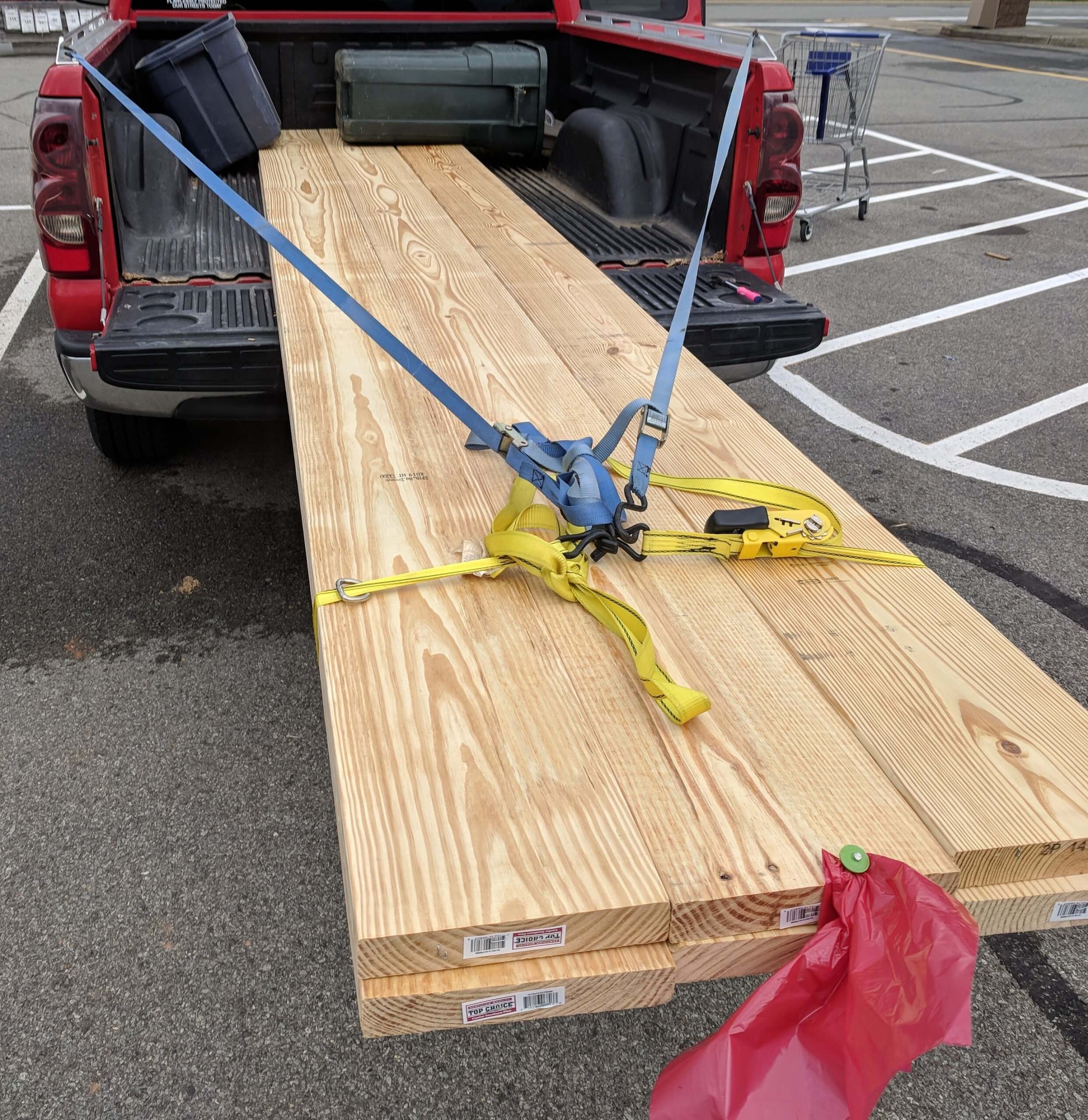
So I went to the big box store and sorted through the structural lumber piles for clear and straight SYP. Here is the key: Don’t have a size in mind, just make certain you can get two bench top pieces out of your width. Since I was going for 4+ inches thick, any 10″ board would work. I bought long ones, short ones and wider ones. The goal was to get clear wood cheap. 2X4s, 2X6s and 2X8s are likely to be fir or spruce or something often branded as “whitewood”. It is not SYP. Don’t buy it. The larger items sold for floor and roof joists are SYP and will say so.
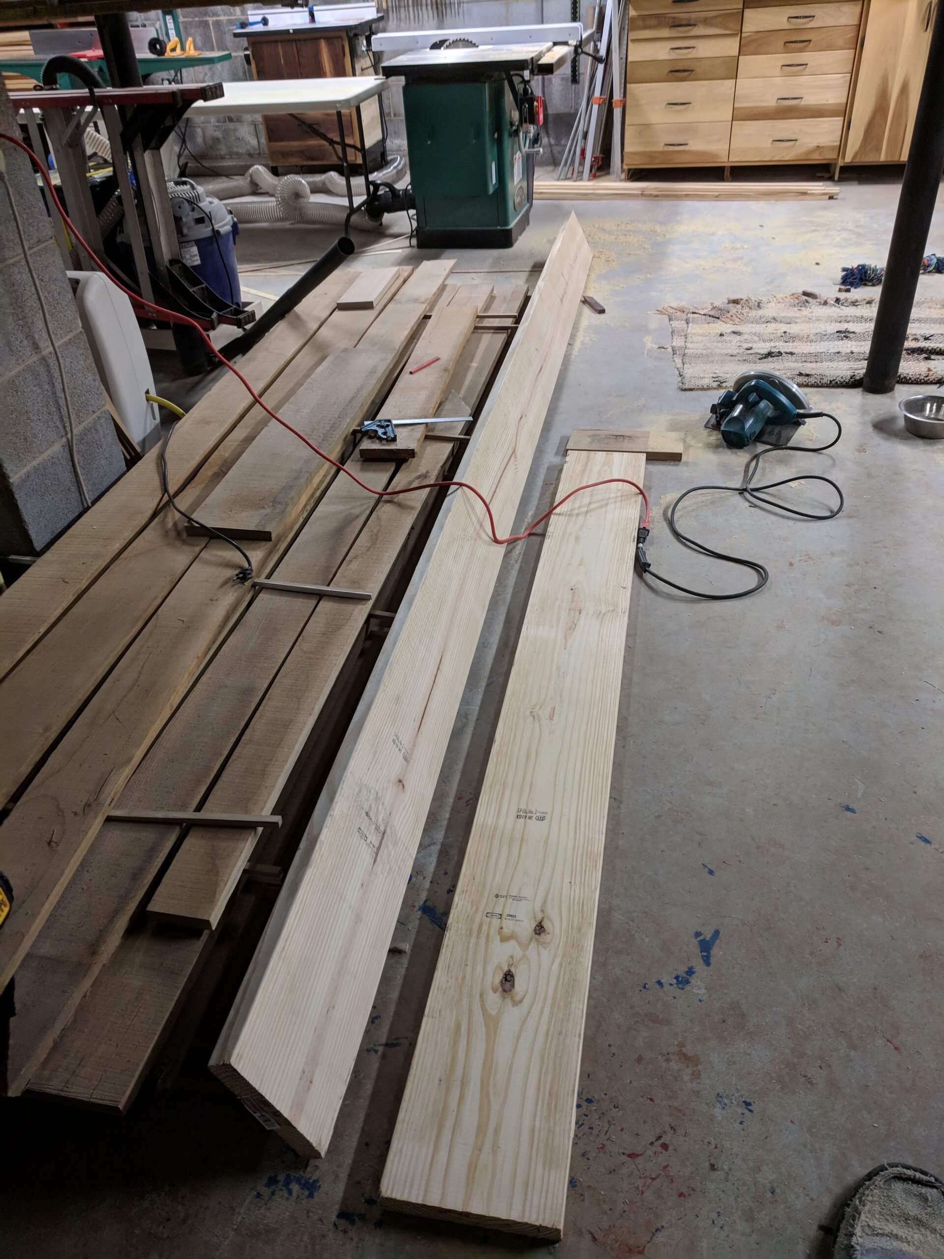
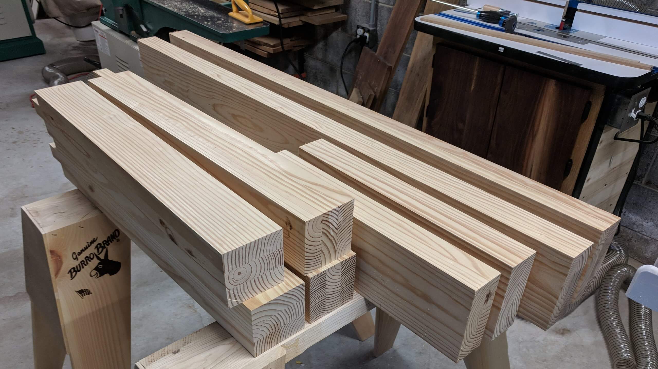
I found a number of 14′ boards that were pretty clear. They also measured 14’1″ and that really cemented the 7′ design as I was open to 6′ if needed. I cut them to rough length. I then ripped off the “convenience” edge on the table saw and ripped out two 4 1/2″ boards leaving the second convenience edge behind.
Bench Top
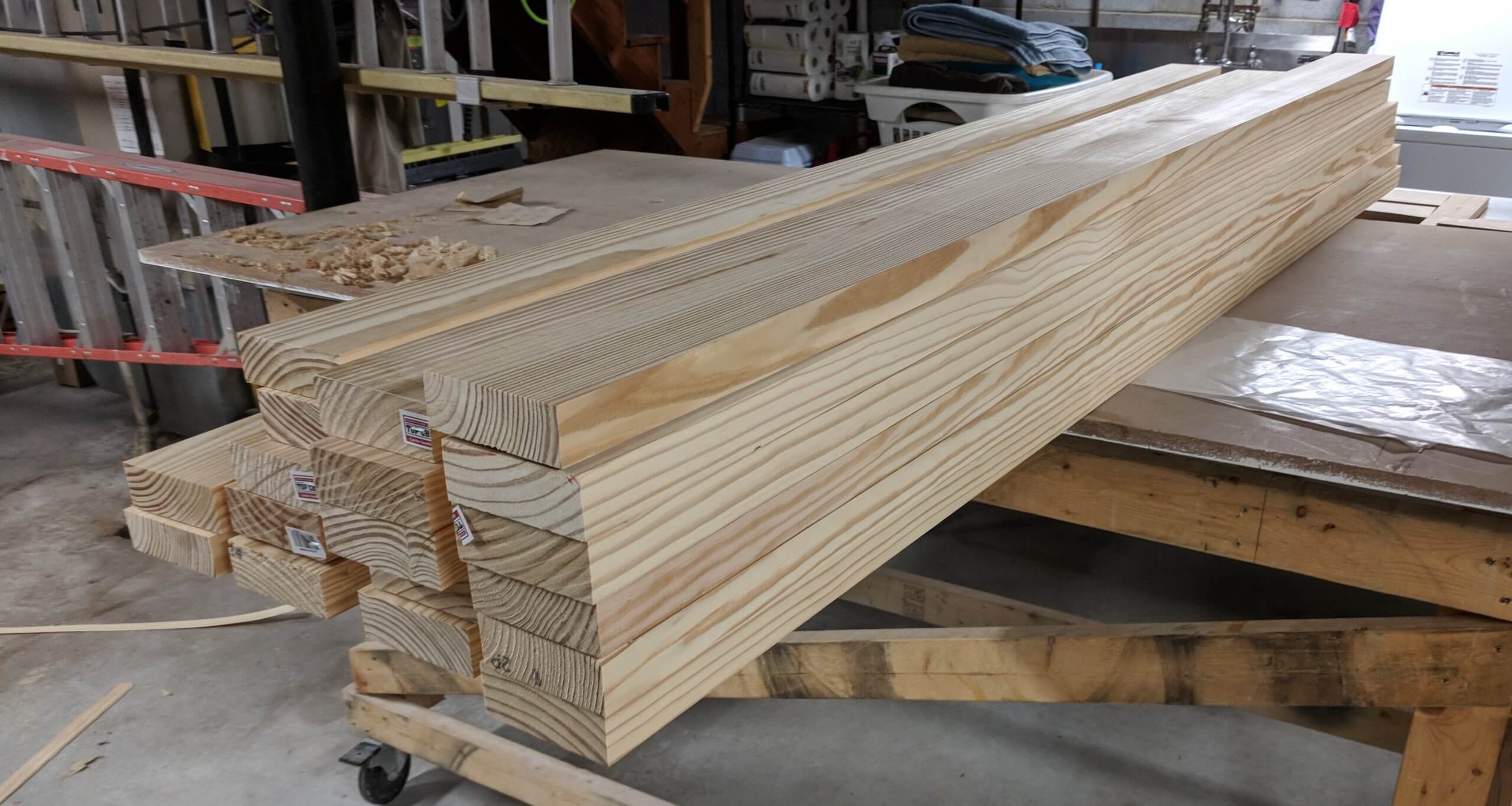
I won’t bore you with images of processing raw wood. It is standard wood prep and this is not about that. Suffice to say the rough ripped lumber was first jointed to give a flat side then a square side. From there they were planned until the other sides were parallel. Here is where not having a set dimension in mind will help. How thick will the top be? The thickness that can be cleanly pulled from the worst board. They all started at 4 1/2″, but when the dust settled the smallest after jointing was 4 1/4″. No worries. Also, when stacked they formed a 25″ deep top vs a 26″ deep one as a good bit was lost to the planner. Again, no worries. 25″ was fine.
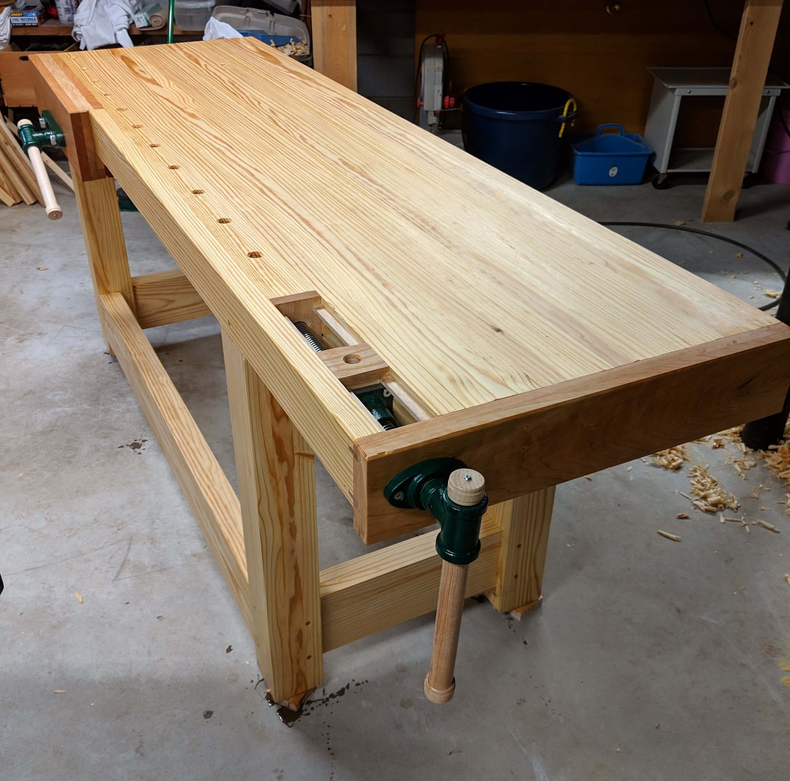
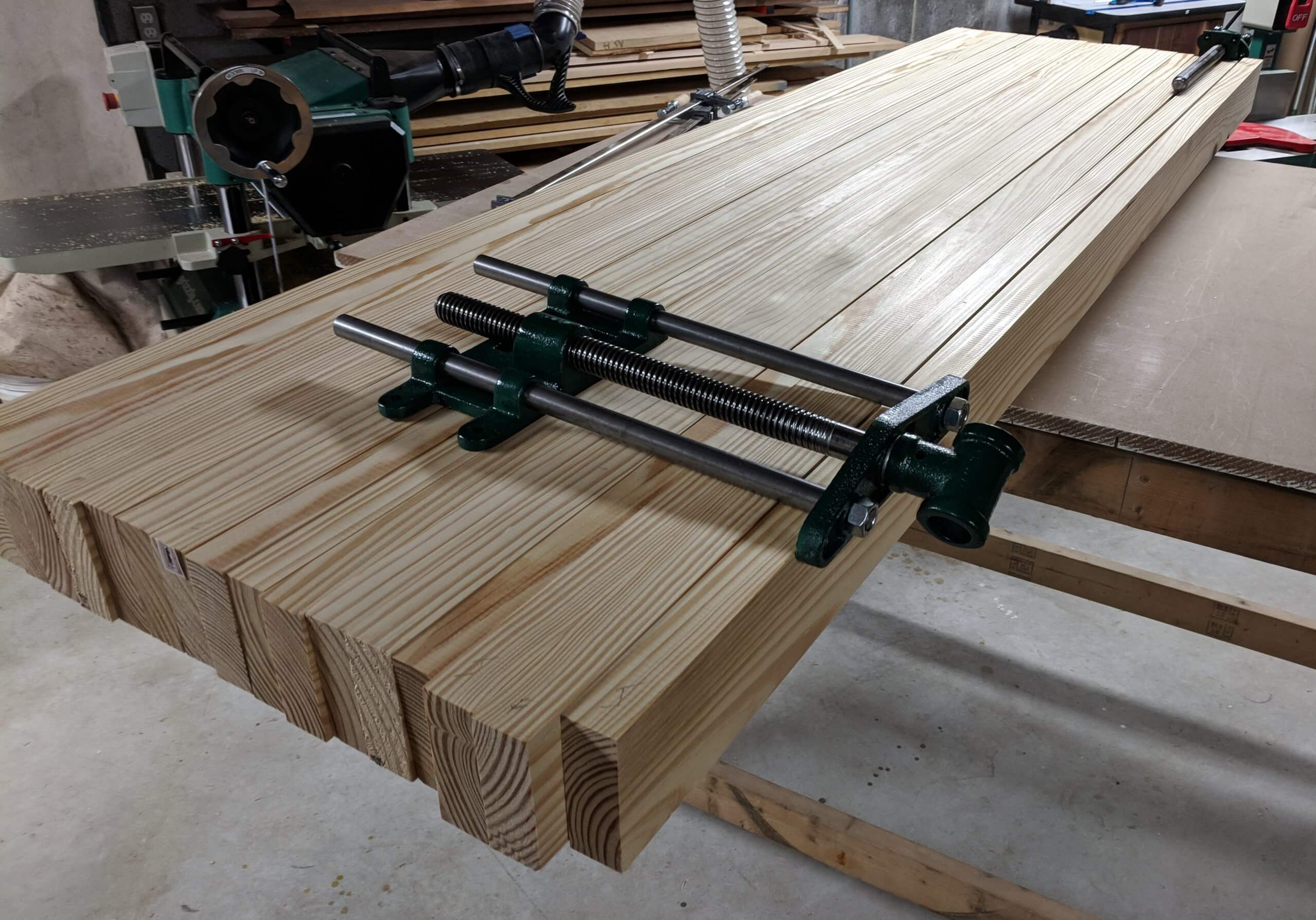
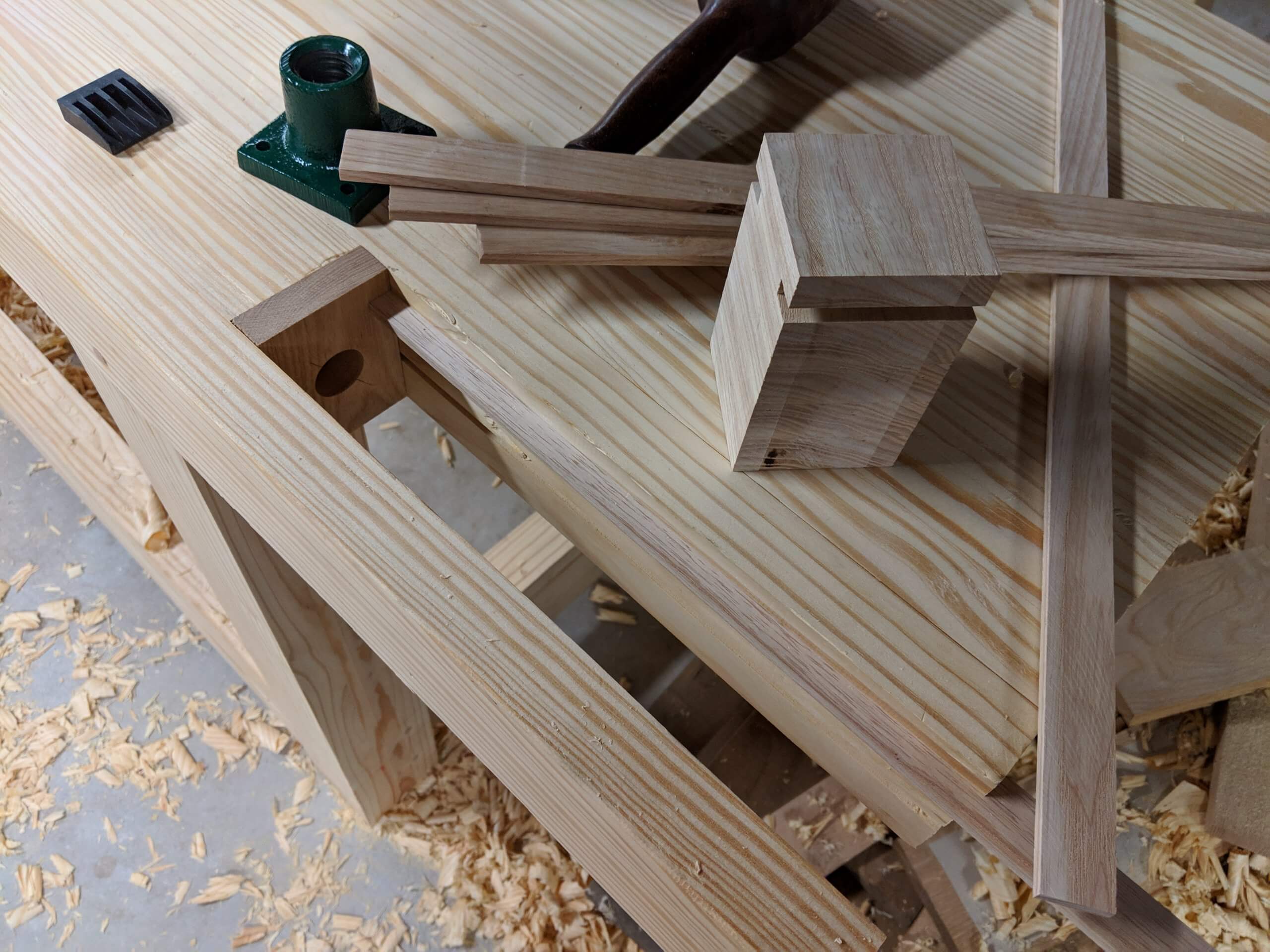
I bought a larger Veritas front vise and a Veritas wagon vise. These are tough, durable, a time honored design and affordable. Since we don’t have a plan to stick to, now is the time to lay them out so spaces can be cut for them prior to glue up. Here I positioned them where they worked for me. I am right handed so the front vise went on the left and the wagon vise on the other end.
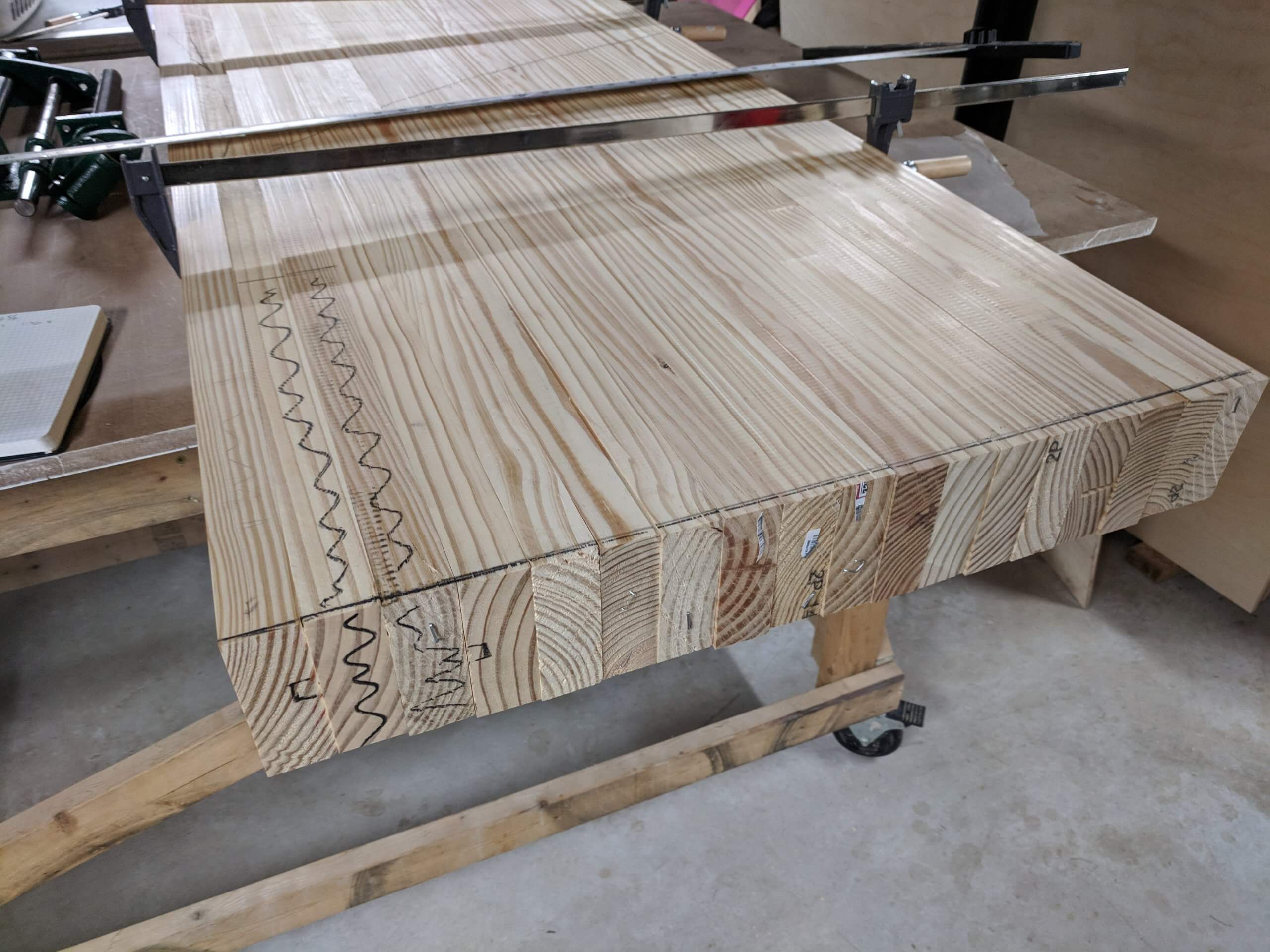
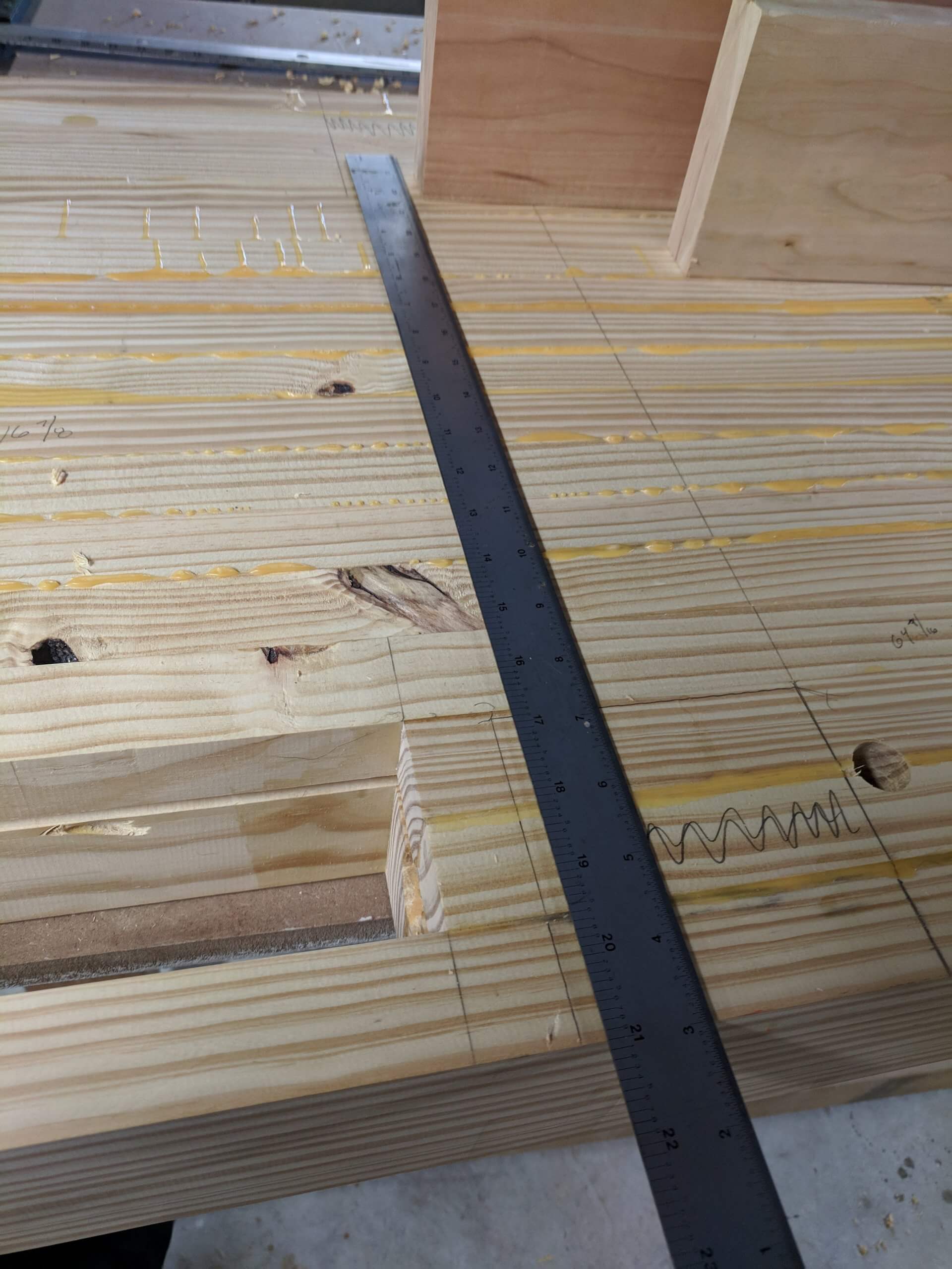
I flipped the top boards so the rings alternated (to prevent warp latter in life) and the best face was to the top. I drew a cabinet makers mark to identify the “up” face and marked the locations for cutouts for the two vises. The standard approach is to glue up the “field” of the top then the vise holding bits then join them. In this case it would be the first four boards that would be fitted for the vises and the rest would be glued as a block.
The first board was cut to make room for the front vise chop, the second and third were shortened to make room for the wagon vise sliding block and the four were glued up as an assembly.
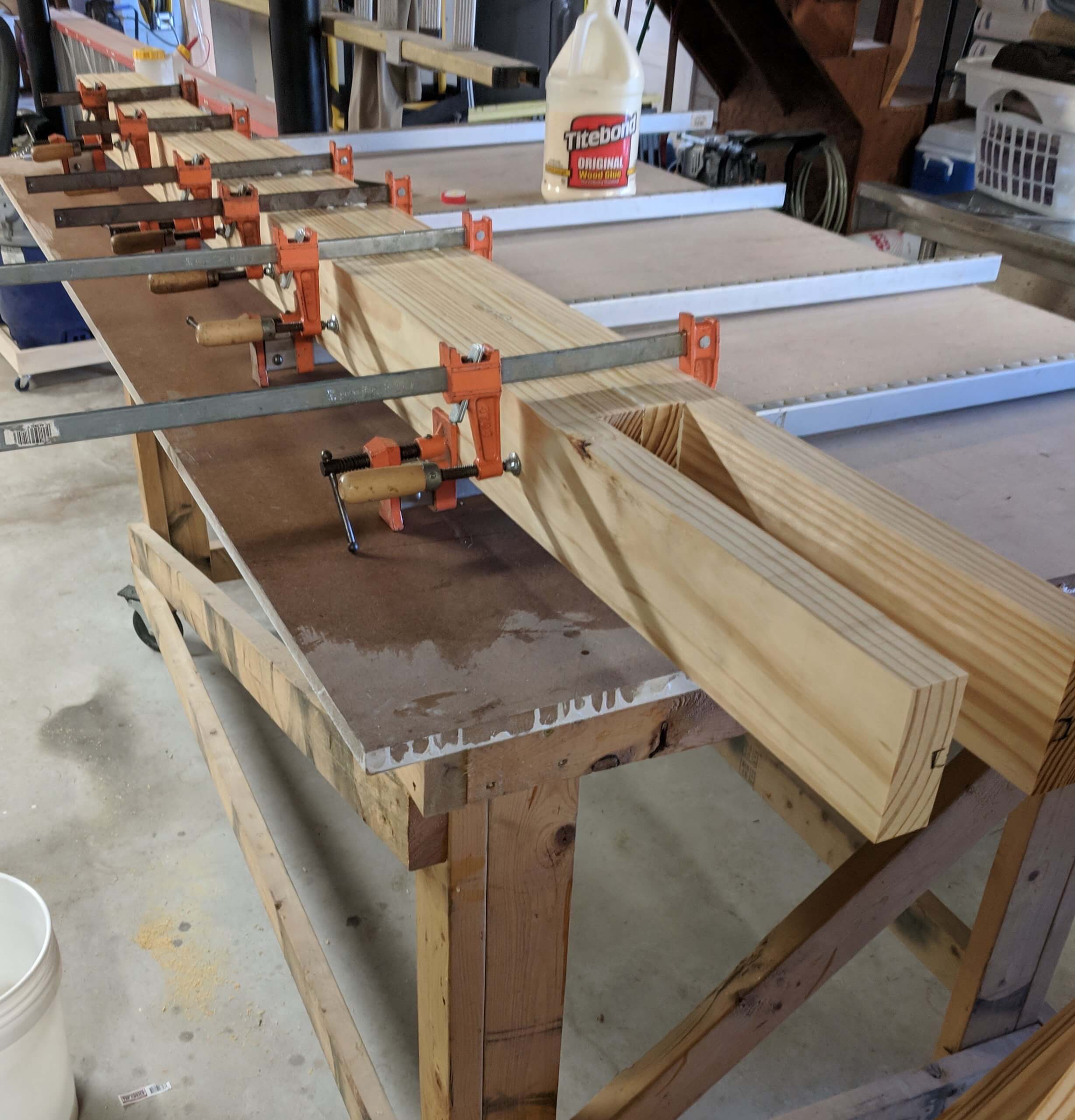
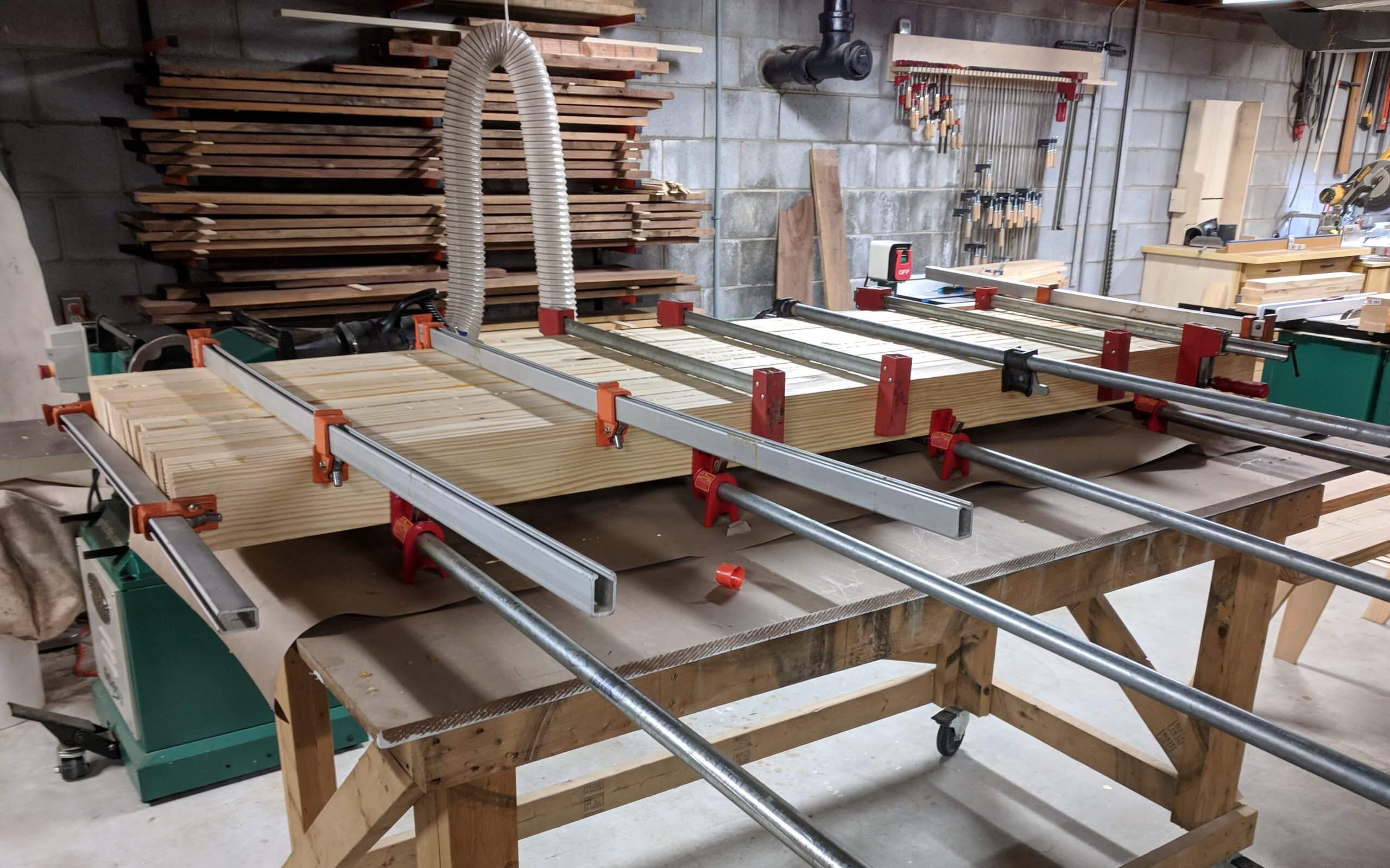
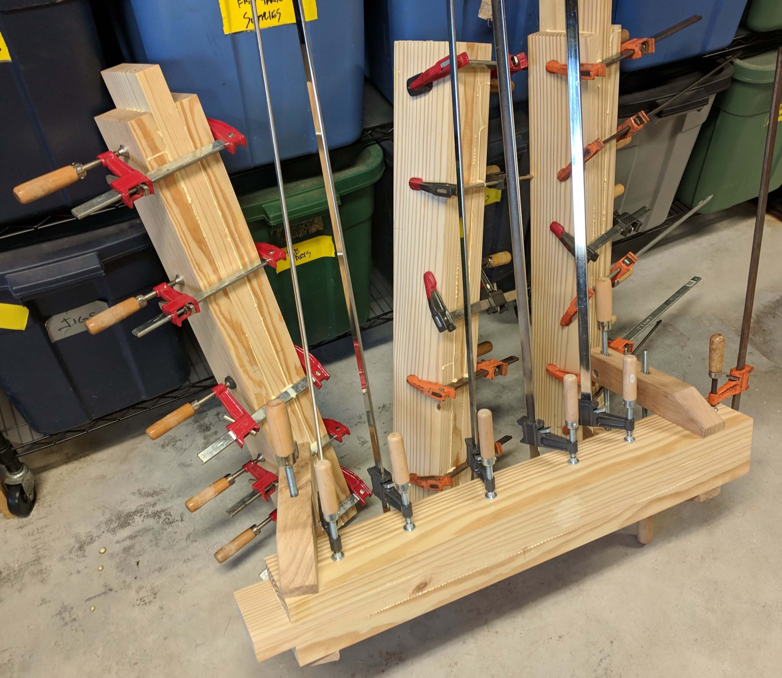
I glued the field boards up in three steps, two groups of six or so then the two groups were joined into one. Some clamps I had not used in a long time were dusted off as you really can’t have too many. You could run these sub-assemblies through the joiner/planner at this point but I really did not want to beat up my blades with such work and knew I could just as easily hand plane the top.
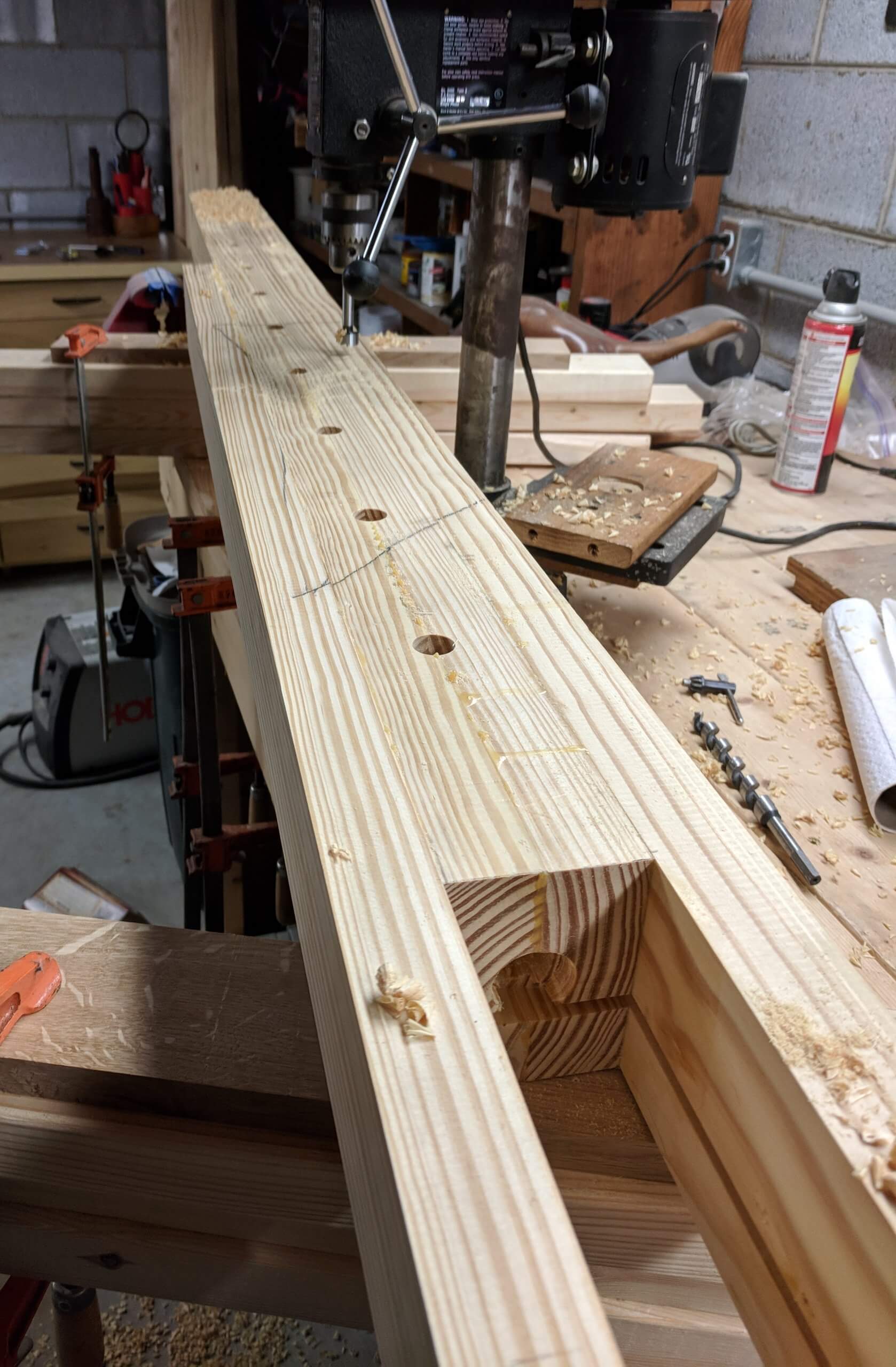
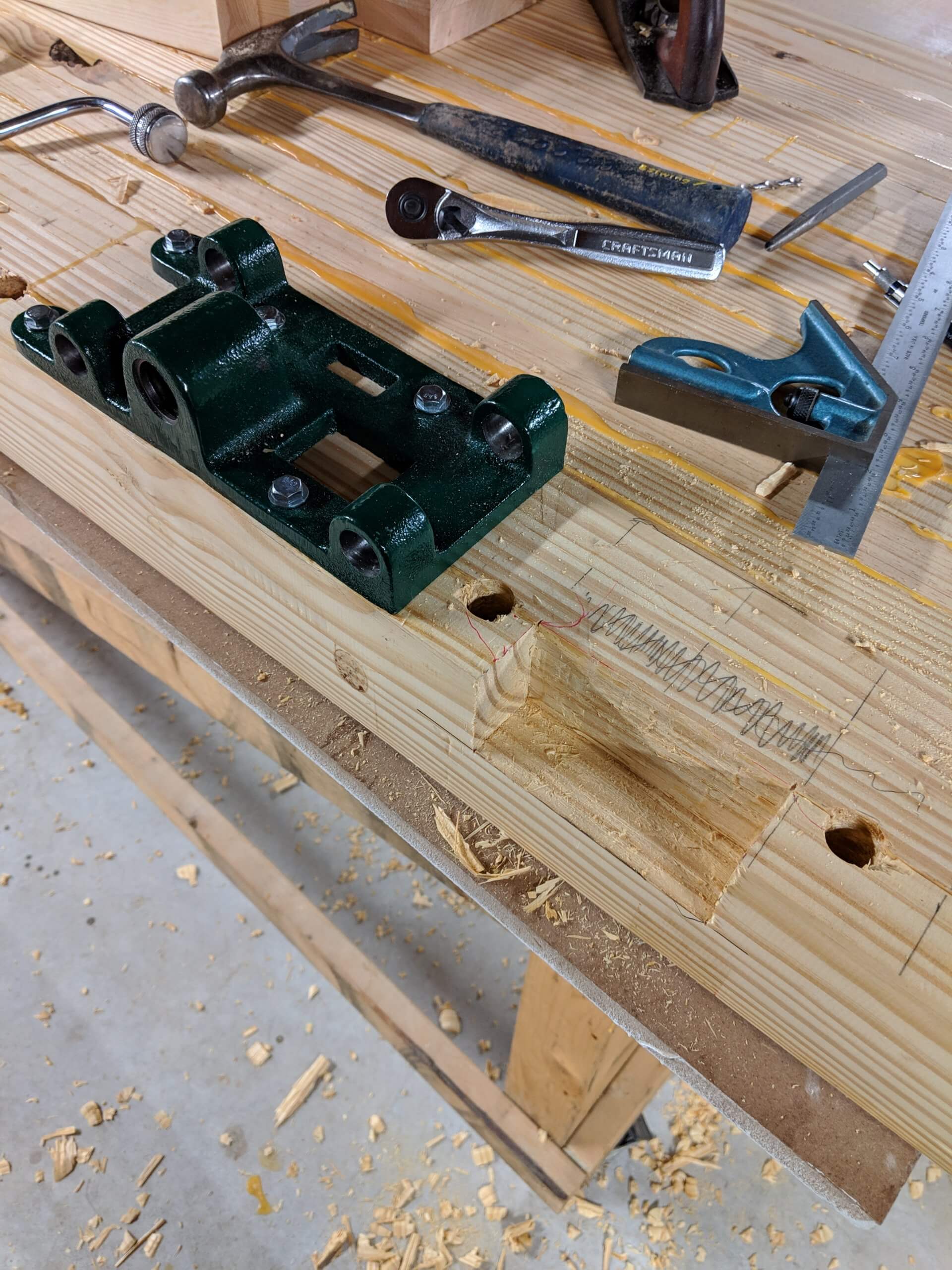
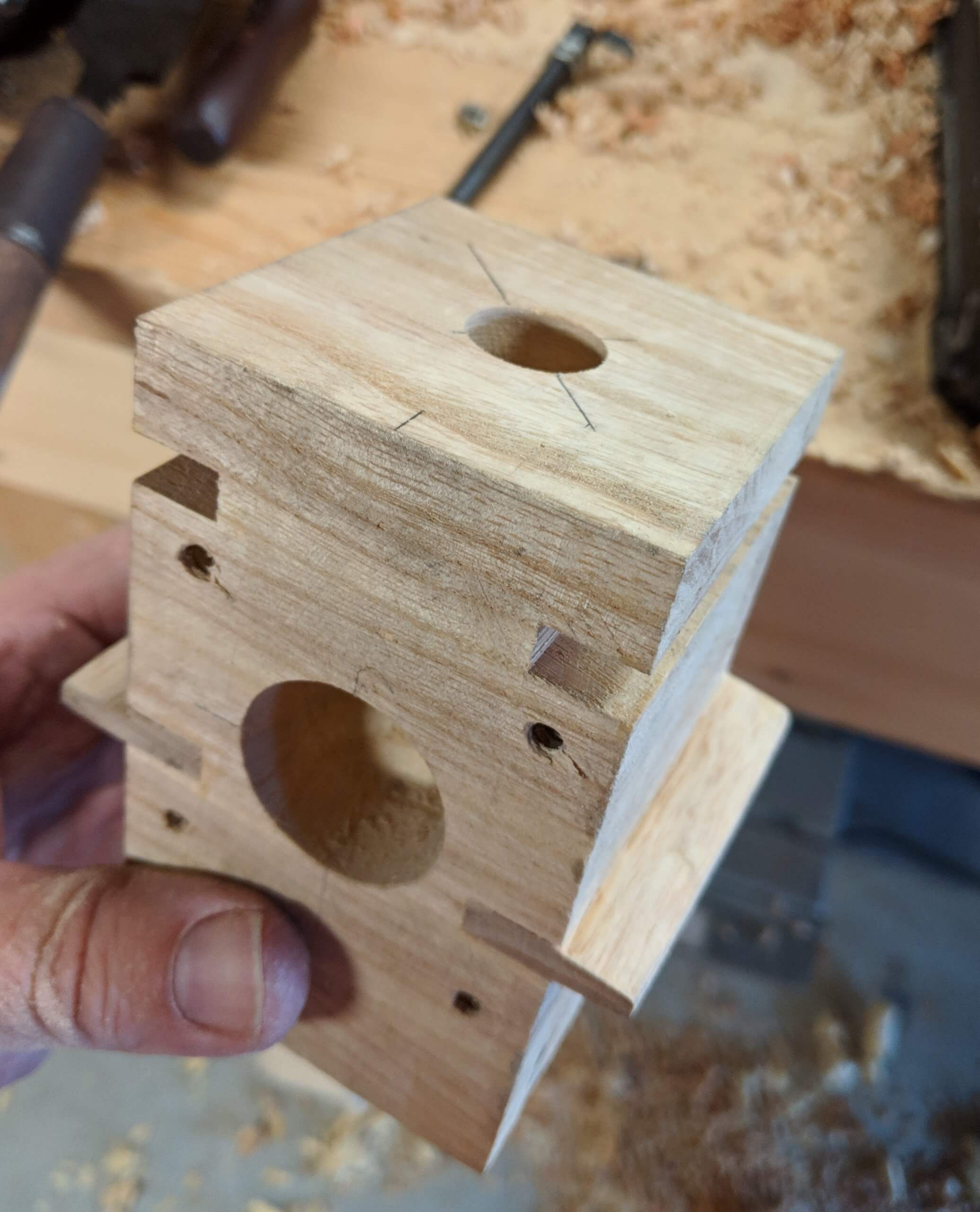
When the four boards for the vise assemblies were dry, I added the dog holes at six inch spacings. I also cut a hole for the wagon vise screw to fit into and routed a channel in the wagon vise slot for rails that the wagon vise block will ride on. My drill press is really really small and the entire process involved a great deal of improvised work holding. The bit and the press also have a 2″ travel limitation so I had to attached an extension to the bit and drill the rest of the way by hand.
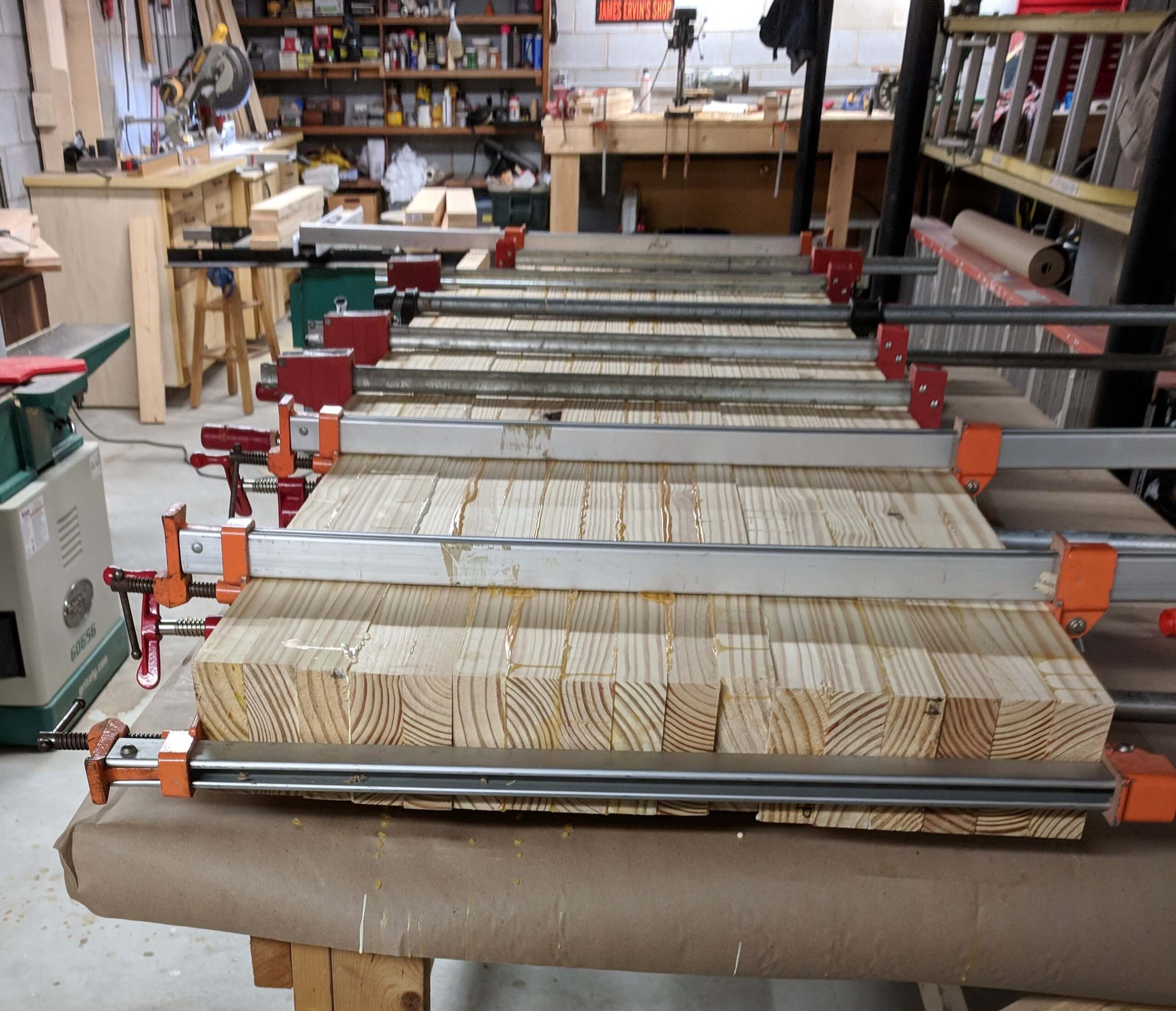
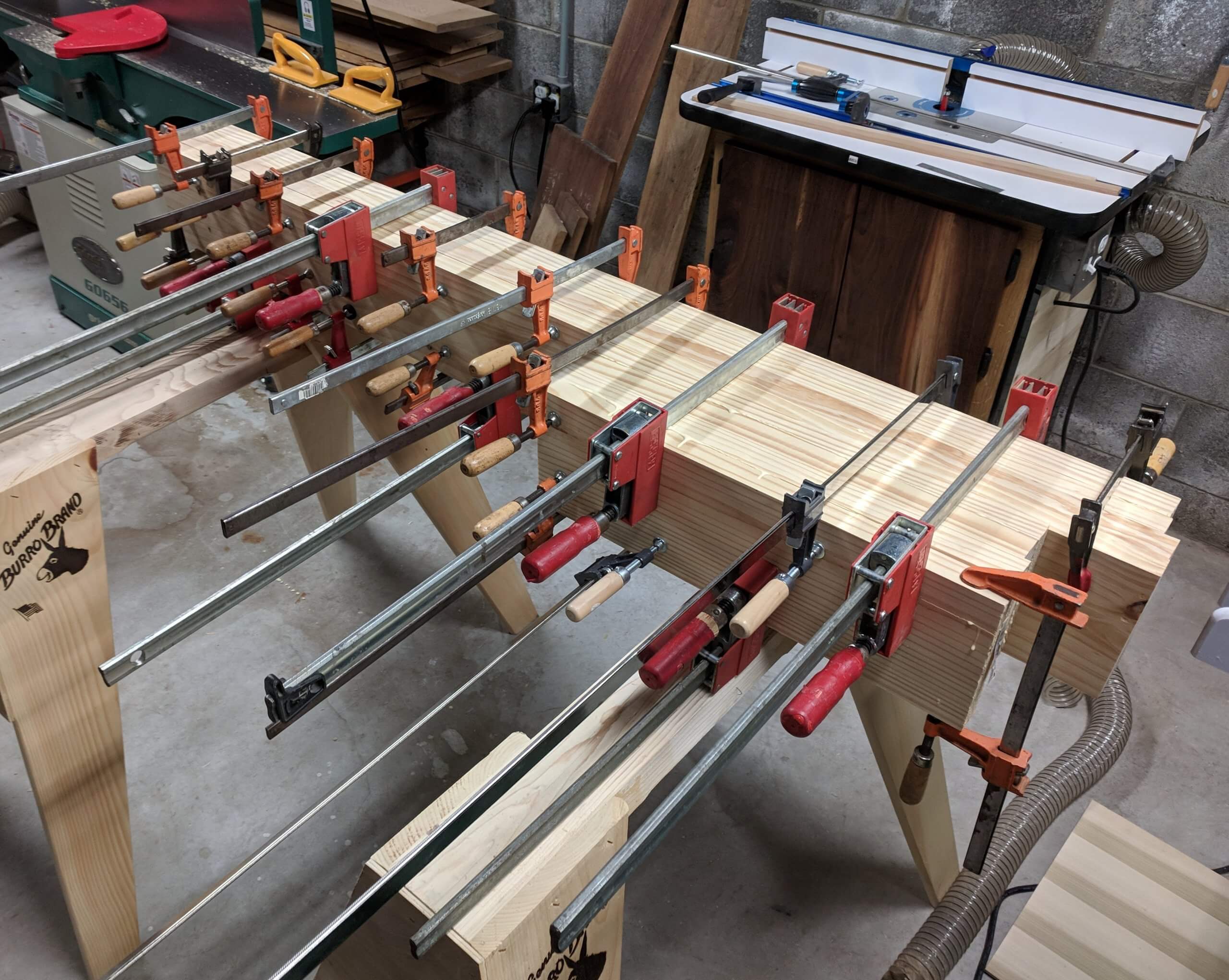
The modified top section with dog holes and vise cutouts was then joined to the open field section of the top, again using about every large clamp I have.

Vise Chops
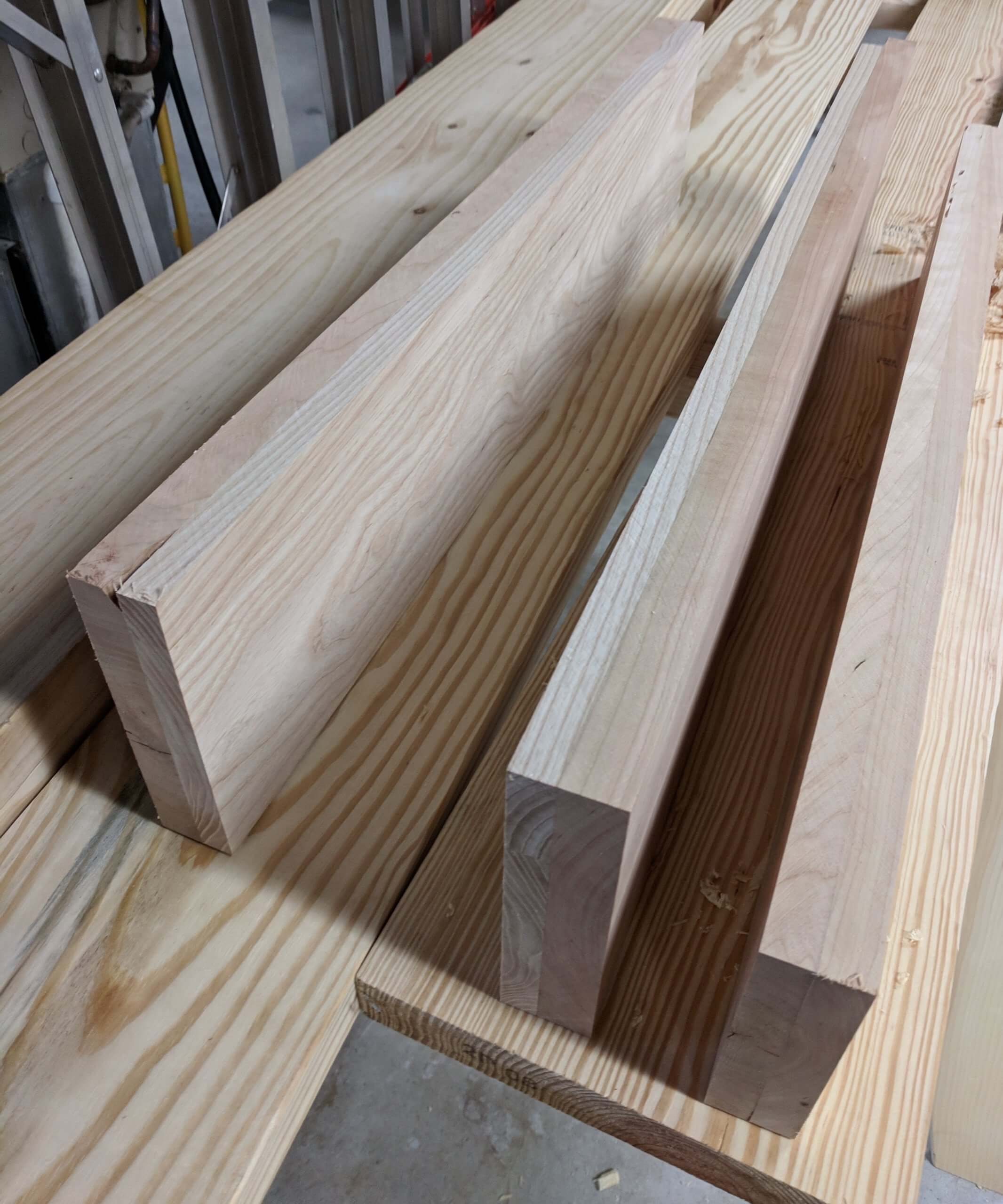
While the top was drying, I milled up some ash and cherry to make vise chops for the front vise. I could make them now that I had a rough idea of how long they needed to be. The ash is for the working side and the cherry is for the show side. Again, since I was not working from a specific plan, I only needed to make the bench side chop the same thickness as the outer bench top board and that was easy enough on the planner after they were dry. I also glued up a few cherry boards for the end apron that holds the wagon vise to the side of the bench.
The chops and the apron came out good and were jointed and planned to be a single unit. Again the only one with a finished size to shoot for was the the bench mounted chop. All the others were left as thick as could be and all were wider and longer than needed.
Laying Out Legs
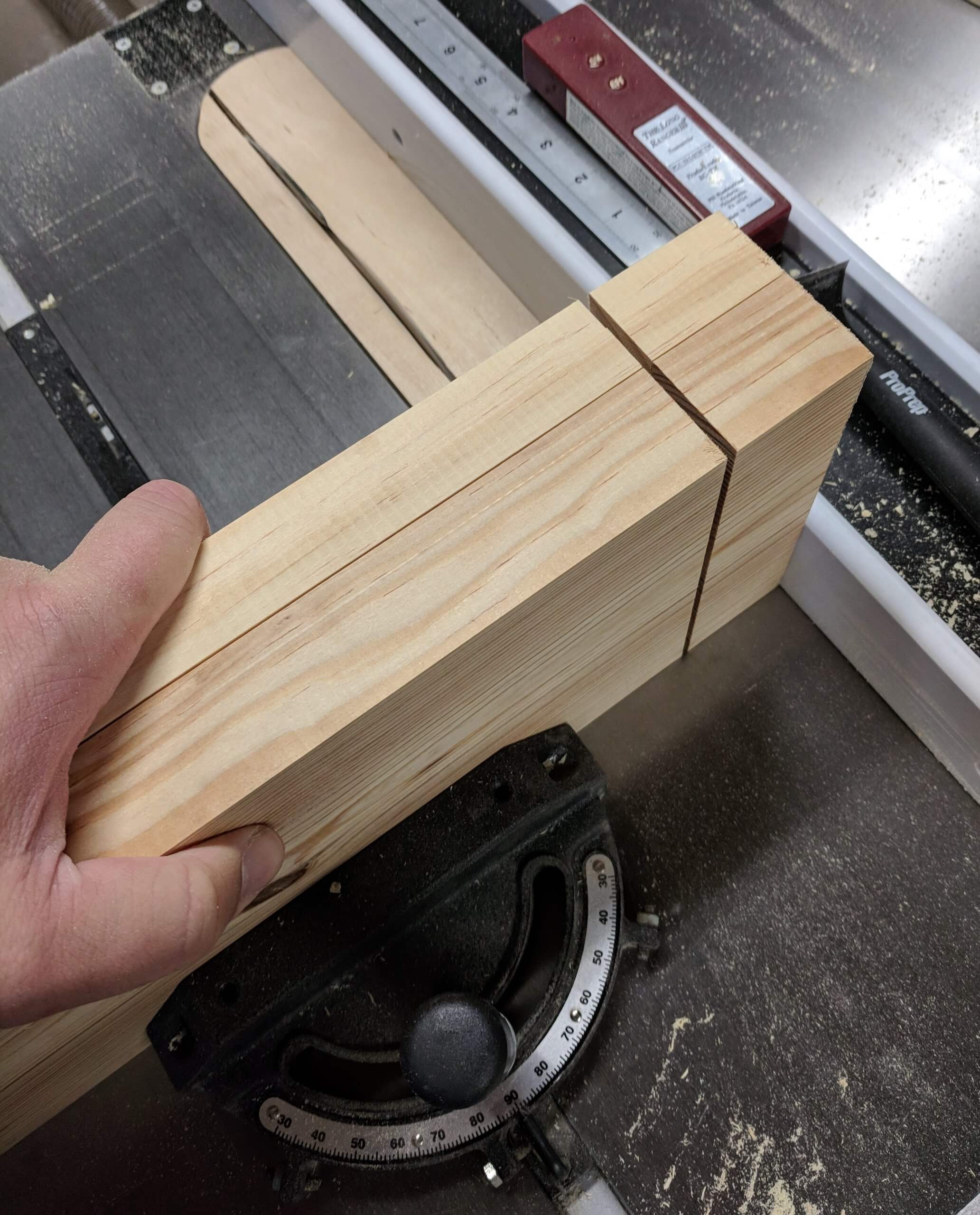
With the top dry and on its face, now was the time to layout the legs. I milled up the same width stock using the same standard methods (ripped, jointed, squared, planned) and rough cut them to 36″ in length. With three of these clamped together I could layout the leg locations on the front of the bench. The left leg, by the front vise was positioned to not cover a dog hole and allow the vise mount to also not cover a dog hole and be generally centered in the opening for the vise. The right leg was positioned so as to not cover a dog hole and to be inboard of the wagon vise mechanism. This is why a “general but flexible” plan was essential as the finished dimensions of the top would have been hard to hit and being able to move the legs in and out as needed at this point made their placement easy. There is one “get it right” element to the legs at this stage and that is that all the stock needs to be the same thickness, so run each through the planner to match the thickness of the thinnest one. Doing that will result in glued up legs that are identical.
With the leg thickness established, the location of the legs could be marked on the underside of the top, the the “theoretical” location of the mortise drawn in. The center portion of the leg glue-up will be left 2″ long to make a natural tenon. Marking where these will be would then allow for the measuring and making of the stretchers. With the leg locations marked, the distance left to right and front to back could be measured, resulting in the length needed for the stretchers (but you will need to add 4″ for two 2″ tenons).
Base
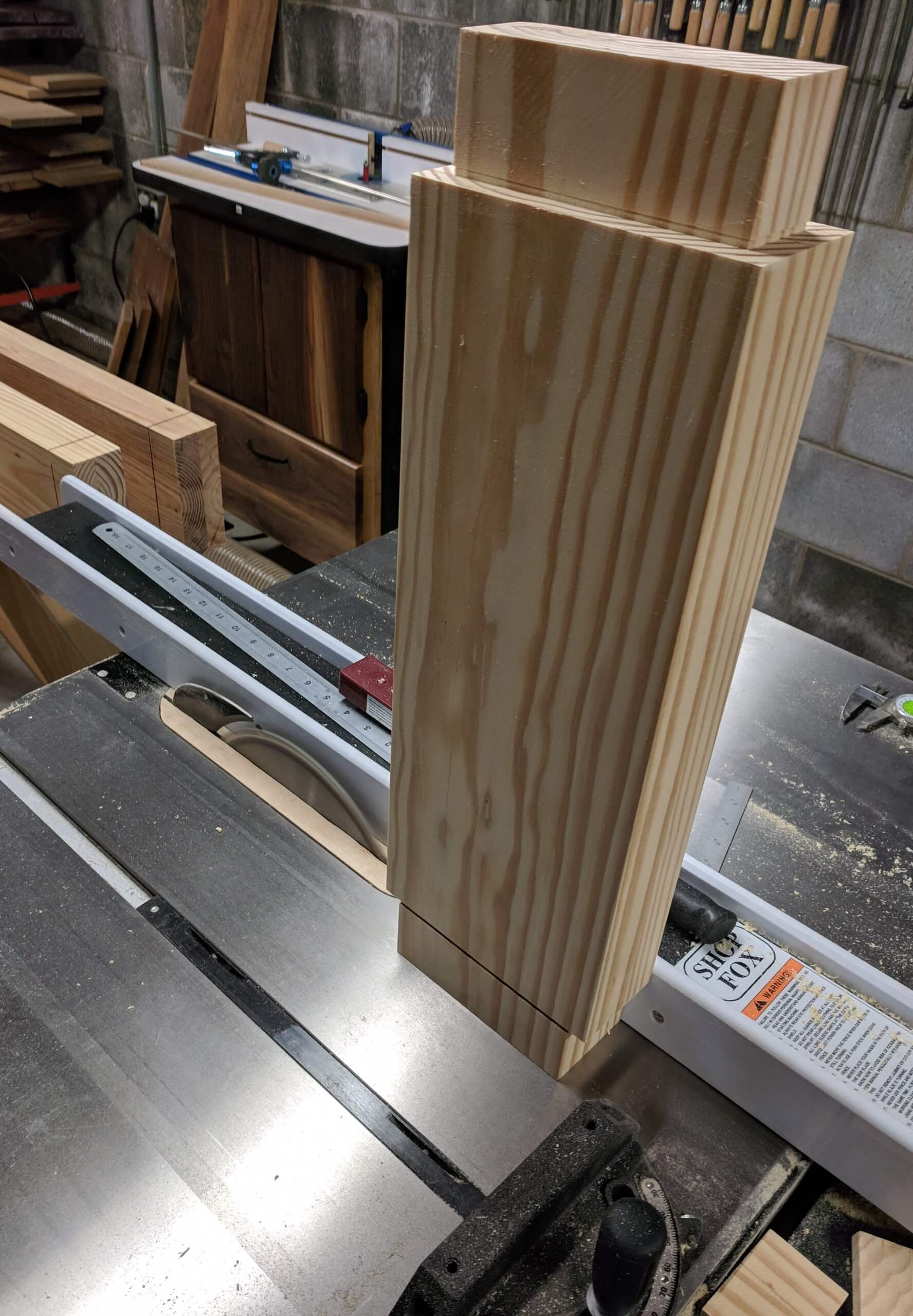
The legs were glued up with the center board extending two inches so that it forms a natural tenon. The only “firm” measurement at this point is the width of the legs as each board is the same thickness. The random glue shift will make legs that are slightly different widths and lengths.
When dry, the legs are milled again so they are all identical in thickness and width, then cut to the exact finished height. The are also passed over the table saw with the blade set to make a cheek cut to clean up any shift in the board when glued so that the tenon is exactly two inches. As before, there is no perfect size, just whatever size is needed to get them all uniform.
The stretchers were milled up using the same methods with the exception that they were not finish ripped, leaving one “width” end wild as they would be joined and planned as a single unit. Here I am gluing all four stretchers at the same time just to save space and clamps. The measurement at this point is the measured distance between the legs from our marking on the upside-down top, plus four inches for two 2″ tenons plus a few inches for final cutting.
After glue-up, the stretchers were milled to final width and thickness. Since I will be cutting all the mortises based on the assumption that the stretchers are the same size, they were all planned to be identical in each direction. Care was taken to use show faces on the outside of the legs and stretchers. Also at this point they were sorted for “best face” and labeled for their position on the bench. The stretchers were also finish cut for length at this point, exactly the amount measured on the top plus 4″ for two 2″ tenons.
Shoulder cuts on all parts were easy with the table saw set to a height of 1/2″ with a 2″ fence spacing from the OUTSIDE of the blade.
Face cuts were also easy for the short stretchers, just reversing the saw setup with a 2″ height of the blade and 1/2″ to the OUTSIDE of the blade.
The face cuts for the front and back stretchers were not as easy as they are really too unwieldy to use the table saw. I marked them with the marking gauge then cut them by hand using a hand saw. I stayed outside the cut line using standard cutting practices then paired them down with a chisel, finishing with a block plane. A bandsaw would have been easier, but I only had four to do so it was not worth the setup time.
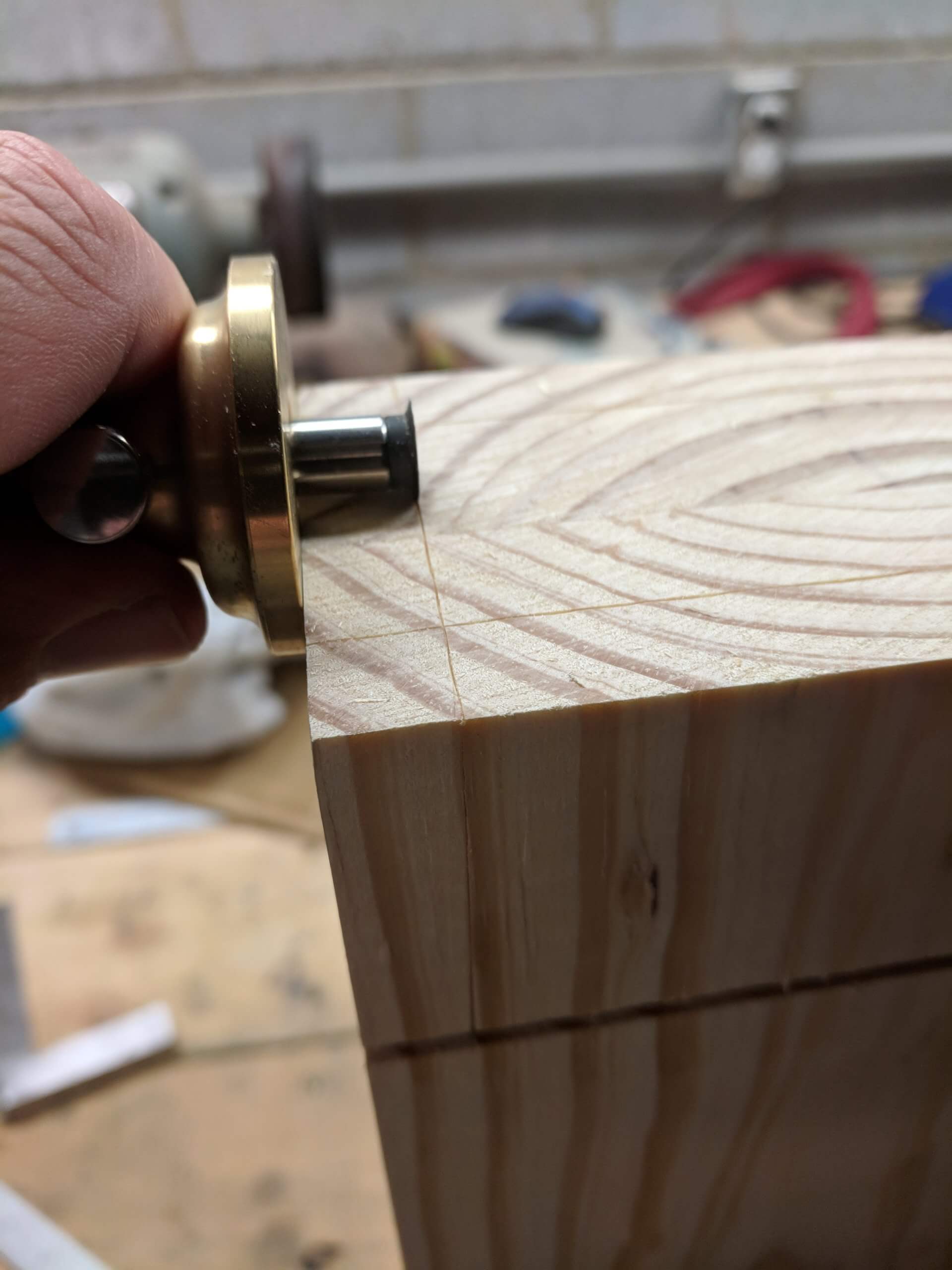
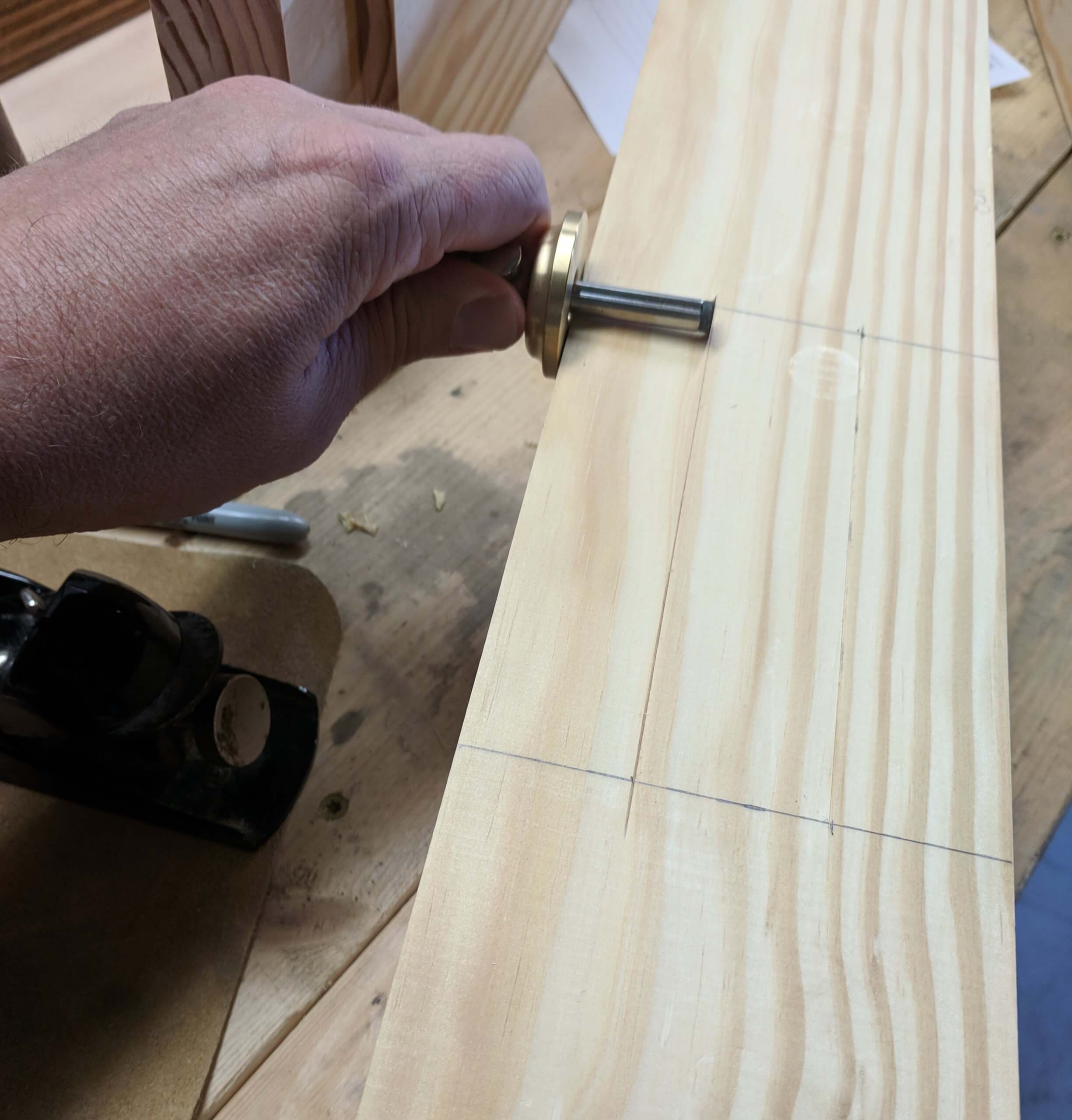
The mortises are laid out using a marking gauge. Setup is the same for all joints due to the fact that I took the time to mill the finished legs to the same width and thickness and the shoulders of the tenons were all machine cut to be identical. The inset spacing for the mortise was determined by (width of leg – (thickness of stretcher -1))/2. So however wide your stretchers ended up, you use that figure. For example, if your stretchers ended up as 3.24″ and your leg face for the mortise was 4.78, the cut line is (4.78 – (3.24 -1))/2 or 1.27″ in from each side. The 1″ you subtract from the stretcher thickness is due to the 1/2″ depth used to make the tenon. Basically you are taking the thickness of the tenon and subtracting it from the thickness of the leg then dividing it by two. This creates a centered mortise. The bottom line for the mortise was determined by how high off the floor I wanted the stretcher to be. In this case I went with 3″ so the cut line was then marked at 3 1/2″ due to the 1/2″ tenon shoulder. The top cut line was then marked a distance up equal to the height of the stretcher minus 1″. This method is used for non-dimensional wood that has been milled until flat vs milled to a certain size and is really easy using a dial caliper. This method is for the side stretchers. The front stretchers are simply cut at the same height, but inset only 1/2″ from the front and back edge as these stretchers are flush with the leg face to allow the use of a deadman or other clamping aid.
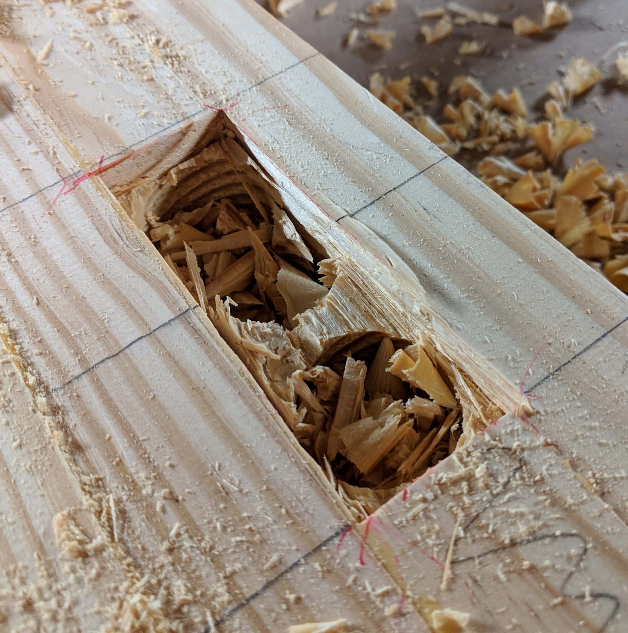
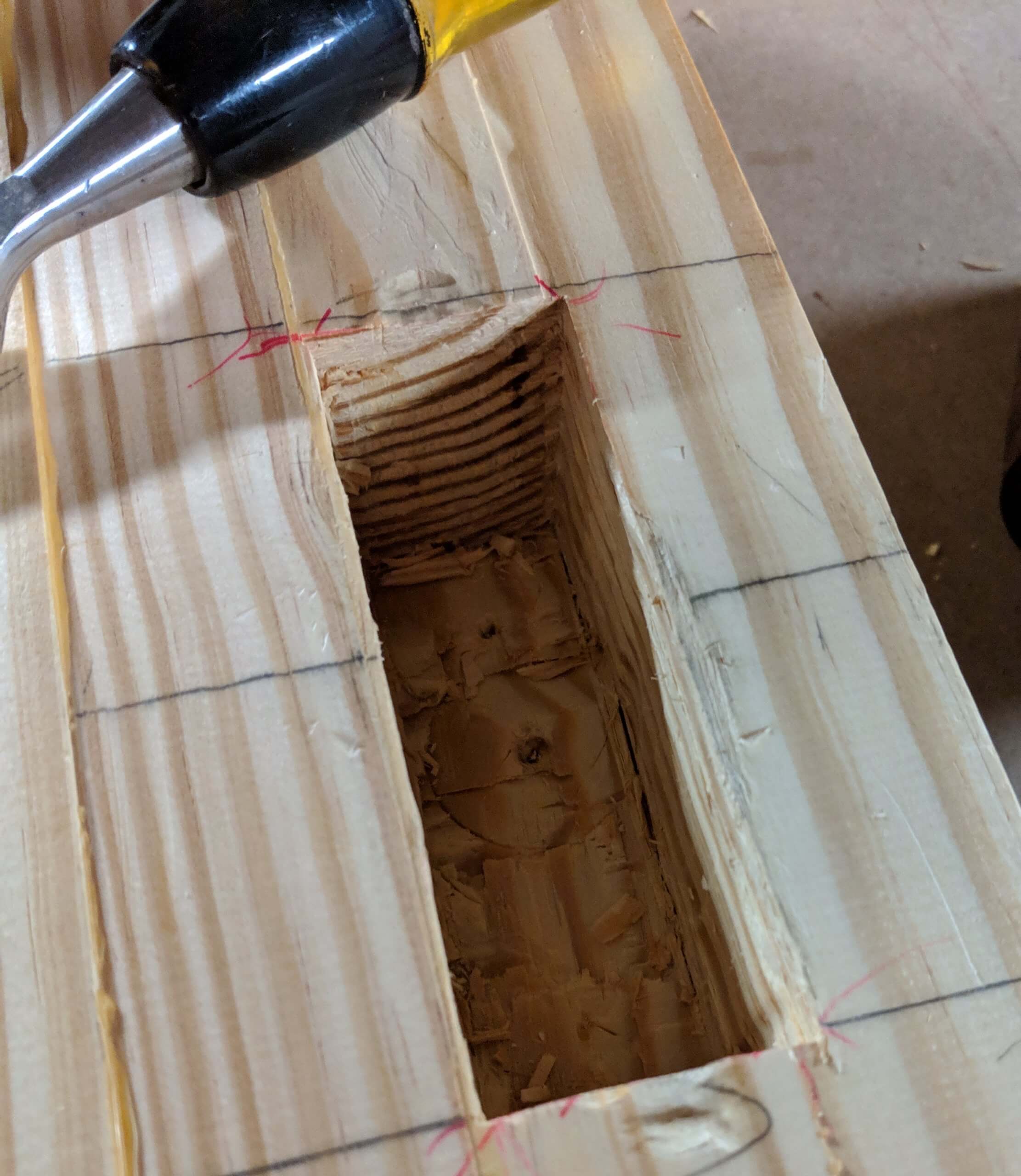
The mortise is cut using whatever method you prefer. I hog out the bulk of the wood using a forstner bit in the drill press then clean the resulting hole out with a chisel. I check with a small square to make certain the sides are straight down and I set the depth o the square to 2 1/6″ so that I can find high spots on the bottom. Prior to fitting the tenon into the mortise, I chamfer the edge so it is easier to fit.
Fit the tenon into the mortise by pairing down the tenon as needed to get a good fit. When you have a snug but not tight fit, check for square. The shoulders were cut with a table saw, so they are square and should rest perfectly square on the leg. If they don’t, there is some obstruction in the mortise. Use an adjustable square set to 2 1/16″ and check all edges, making certain they are 90 degrees to the face and that the entire bottom is at least that depth. If the mortise looks good the rest of the fitting happens with the tenon. I use a small block plane to thin out the tenon as needed, working down to the shoulder with a chisel. When you have it fitting square, mark each part of the joint (I used letters so “A” and “A” for the first joint, “B” and “B” for the second and so forth). You have to do this as each joint is now fitted to each other.
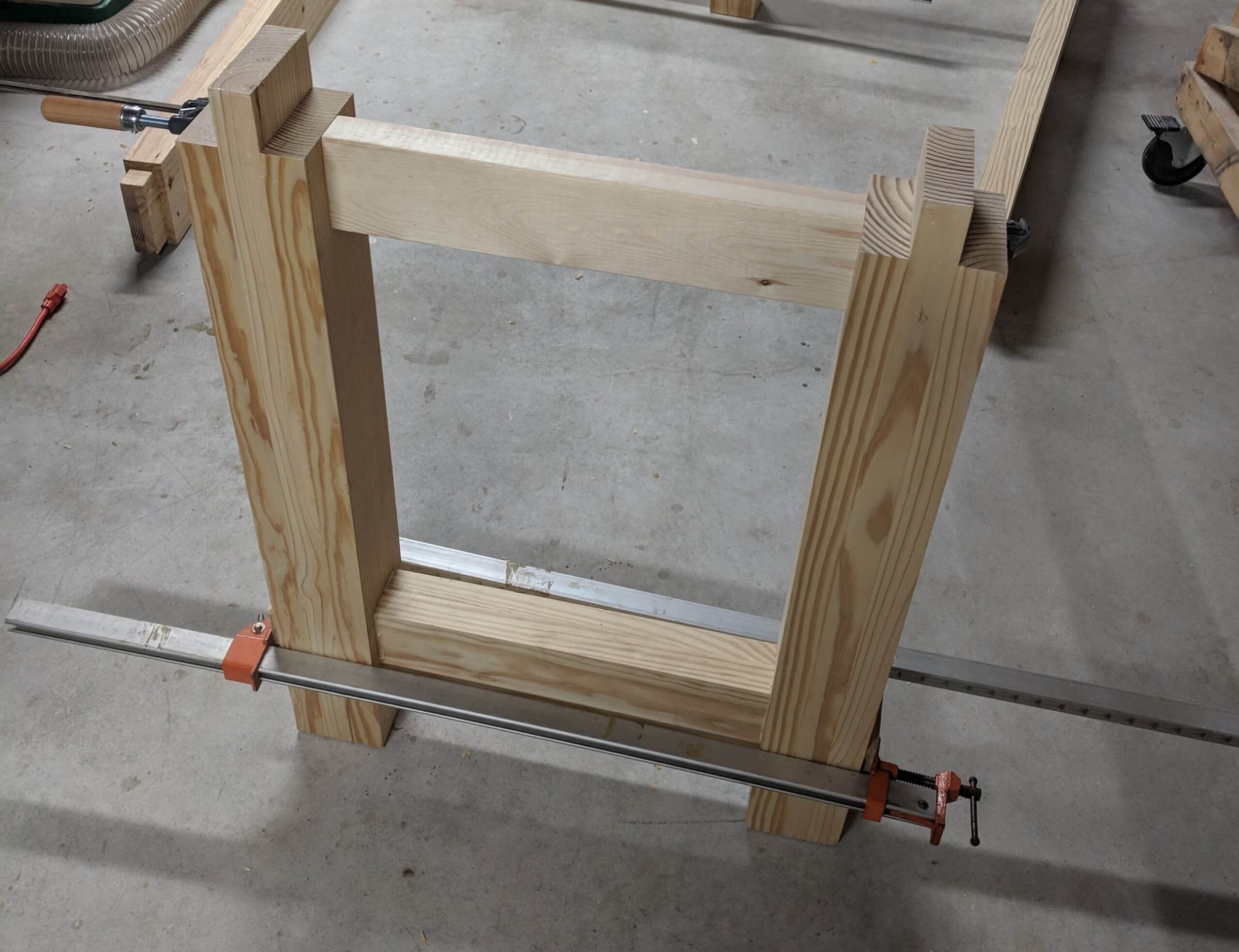
I glued the legs up in pairs, using the short stretcher. Note that I put in a spacer at the top the same length as the stretcher so that the glue up would be square. Once dry I flipped them up and put a 45 degree chamfer on each foot to avoid chip-out when moving the table.
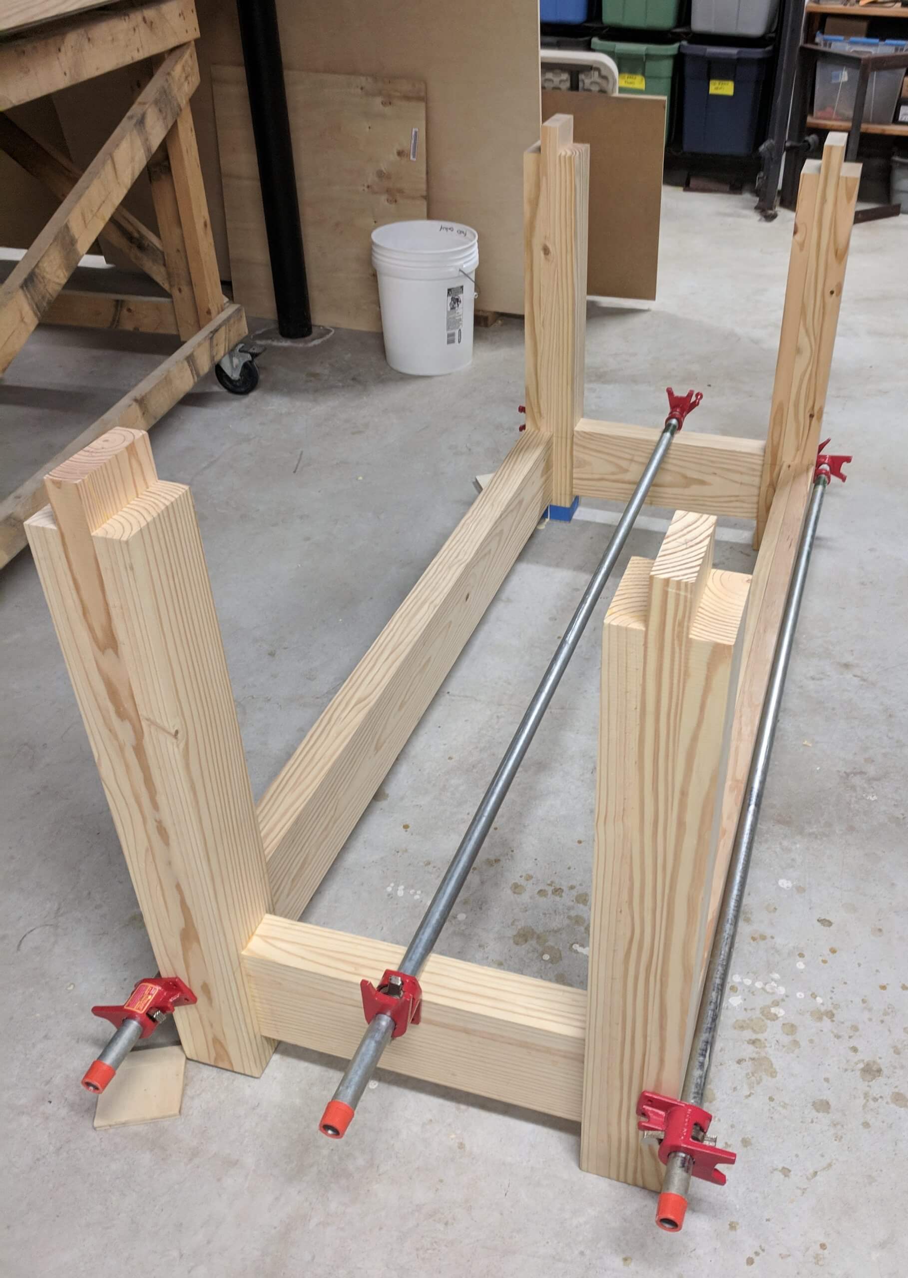
The two leg assemblies can then be joined together with the long stretchers for the front and back. Here is where I made one of a handful of errors. Best practices for milling wood is to rough mill (joiner and planner) then let it sit overnight as it will often move (bow or twist) when the internal stresses of the wood is released by milling. I did not do this for the stretchers and on top of that I let them sit a few days in the shop before gluing them up. The end result is that one of them developed a twist, so the two tenons were not in the same plane. I was able to force it in to the mortises but it introduced a slight rack to the base.
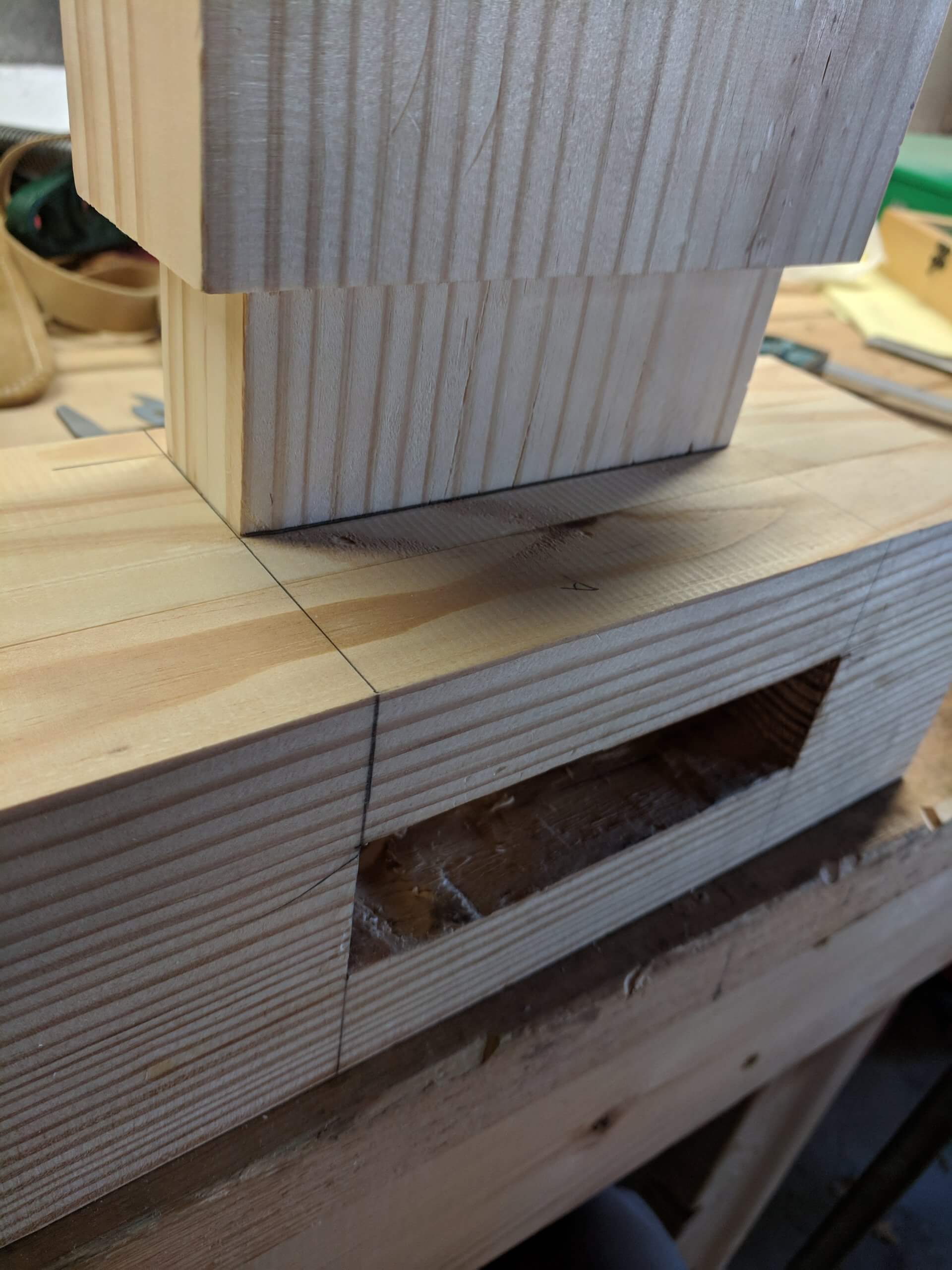
Partly to counteract the twist and as it was essential for the next step, I placed the top right-side-up onto the drying leg assembly. I had to get the Hulk to come over and help (that is me when I am doing stupid things like moving a 200 pound chunk of wood). Move the top into the exact position you will want it (in my case flush with the front face with the legs where originally marked on the underside. Mark around the protruding tenons with a different color marker. I used black for the layout lines, so I used red to mark the actual locations.
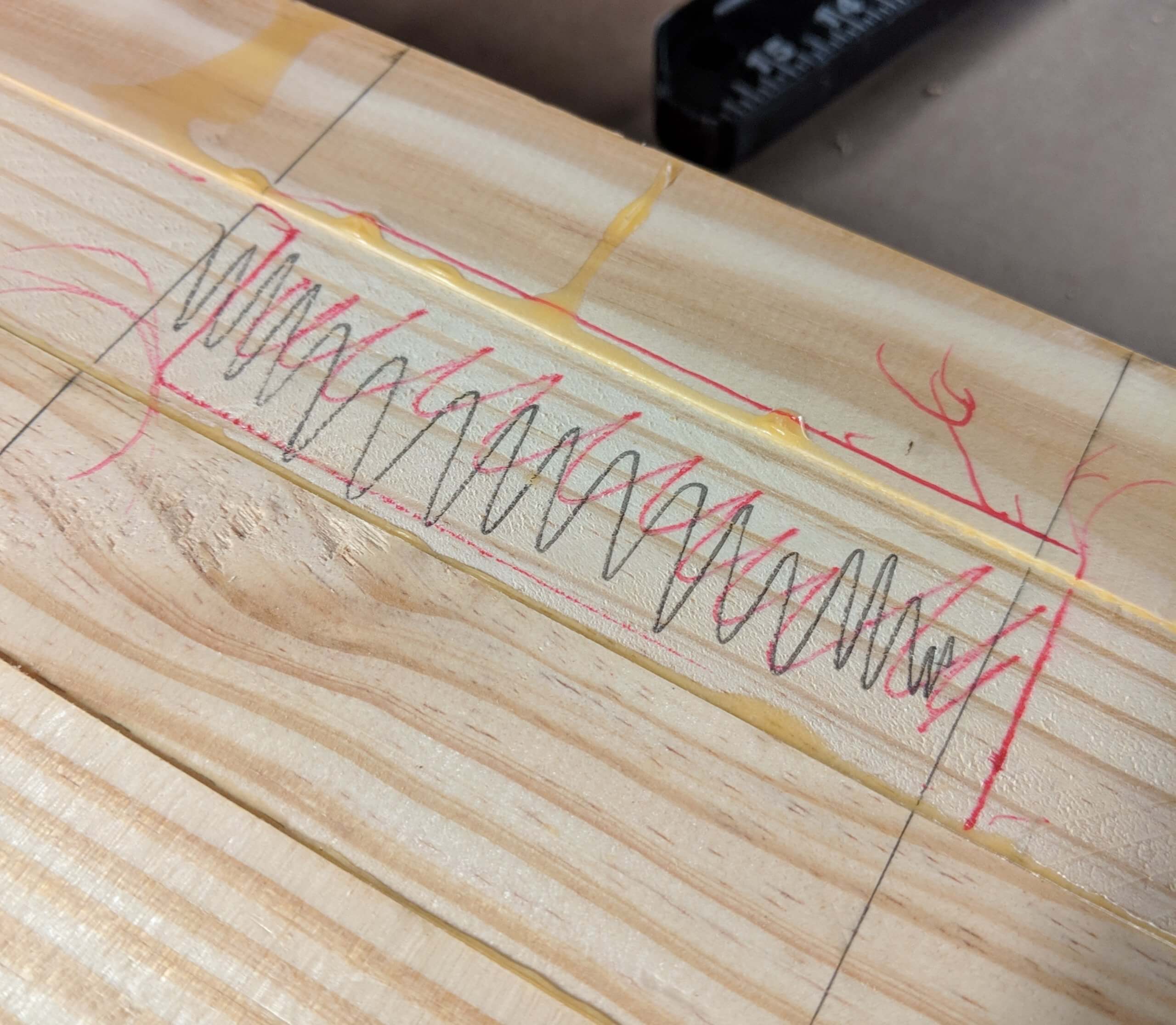
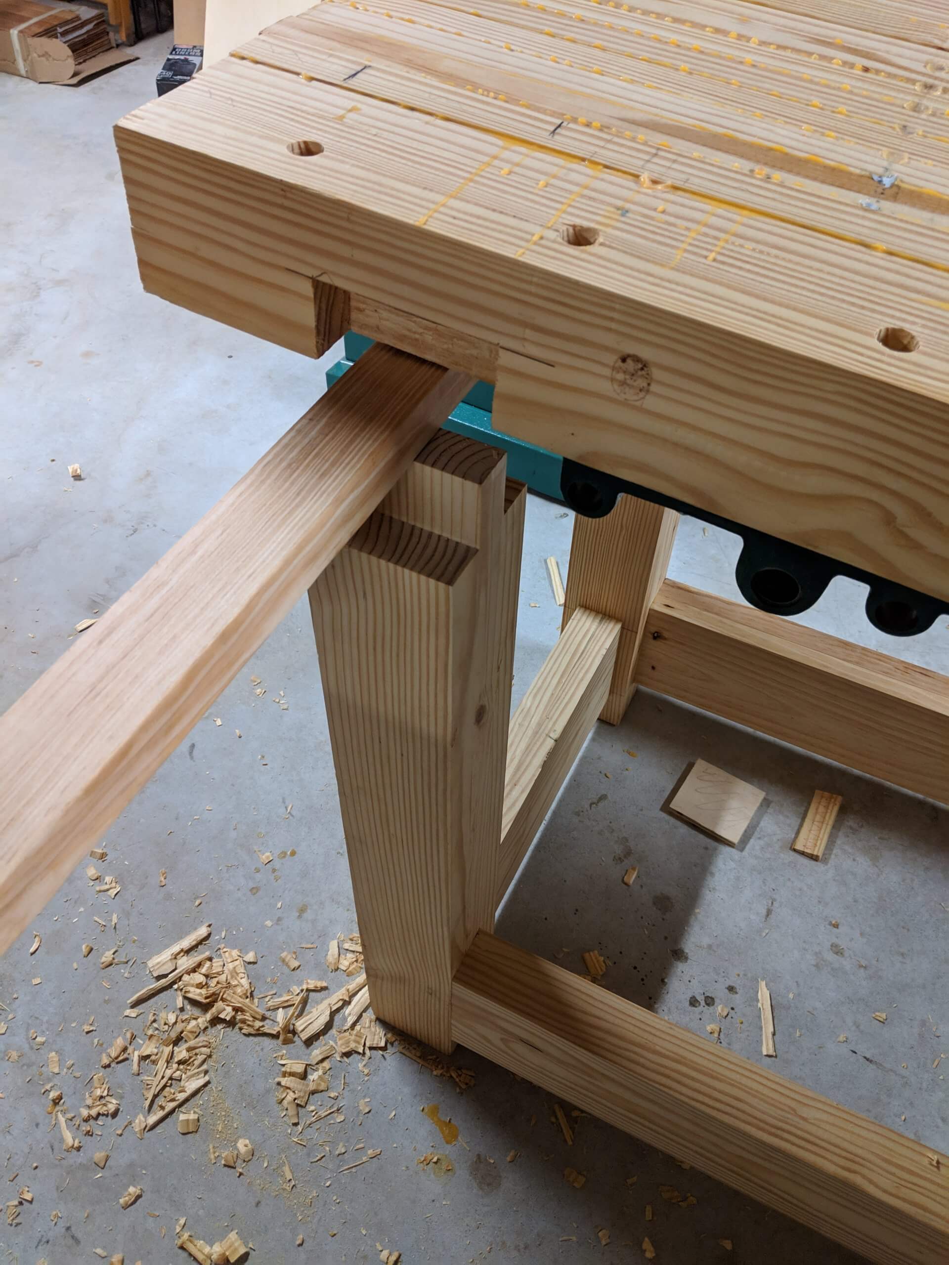
In a perfect world the marked locations would line up with the calculated locations, but the aforementioned twist in the rear stretcher slightly translated to the position of the top tenon in the leg. You can see in the image that the leg is moved slightly to the right and towards the front. I could have cut the mortises where originally planned and pulled the leg back in, but since I was going to be assembling the top by myself, I needed it to more or less drop in, so I skewed the mortise to match the new location on the one leg. The others lined up perfectly.
As before, I hogged out the mortise with a forstner bit, but this time I only cleaned up the cut to a depth of about 3/8″ so I could use a router with a pattern bit.
The pattern bit followed the clean edge of the mortise and made quick work of cleaning out the waste. A good bit of cleanup was still required to get the depth correct and to square the corners. I had to take great care to make certain these mortises were square and to the correct depth as there was no way I could test fit the top as it was too heavy for me to keep moving on and off without help. My plan was to cut the mortises then flip it onto the legs for glue-up in one step versus two or three test fittings for each mortise. To make this work, I cut them larger by about 1/32″ in each direction.
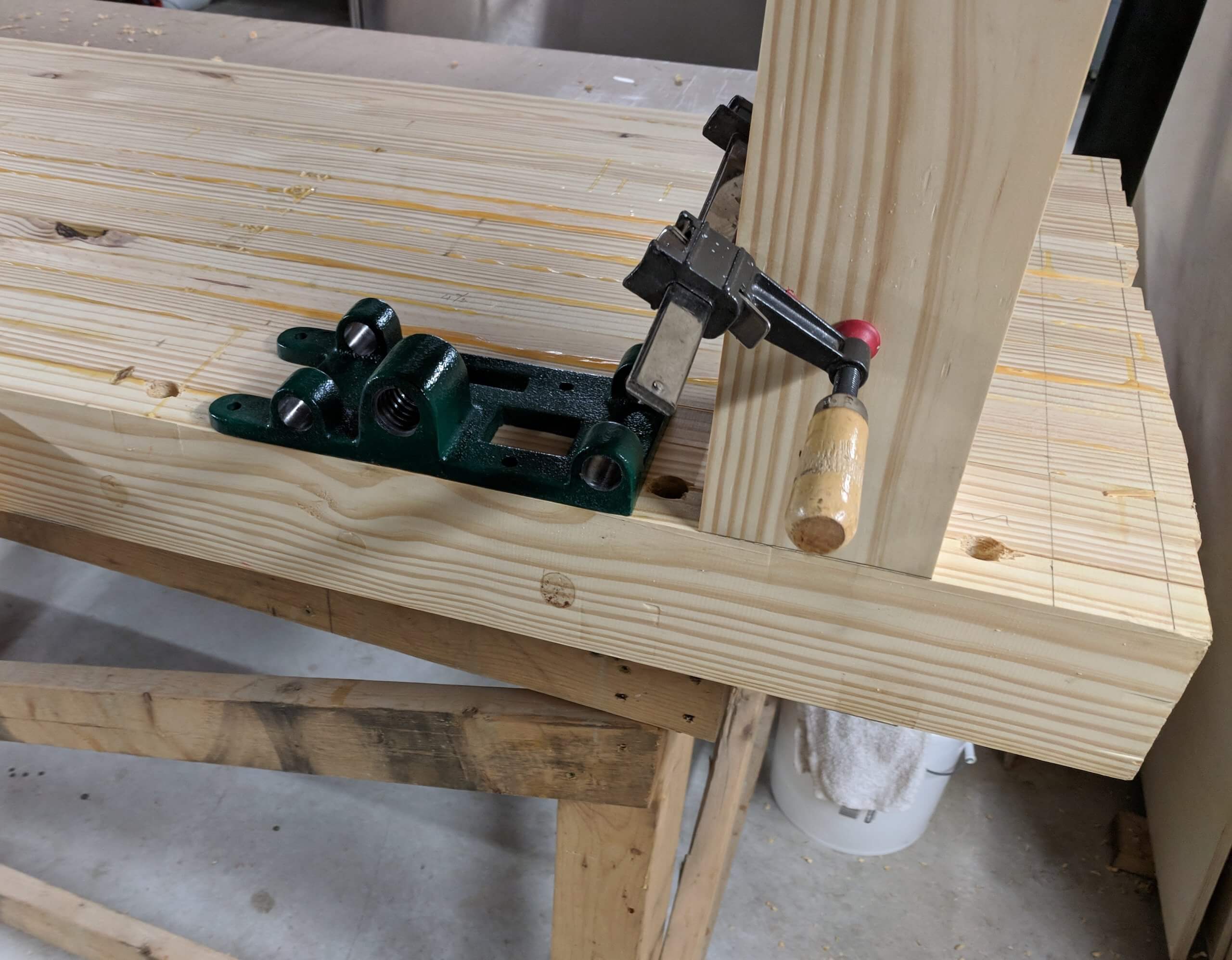
While the top was on its face for the last time, I mounted the front vise in the location previously determined so that the dogs holes were not impacted. The only trick here is to keep it parallel to the bench top and to not protrude past the top face. I kept mine back by 1/16 so the bench mounted chop would rest flat against the bench and not be skewed by the vise hardware.
The top was flipped and it slipped into the mortises without much fuss.
Rather than remove it (the Hulk was getting tired), I used a caul to hold it up off of the tenons so glue could be applied.
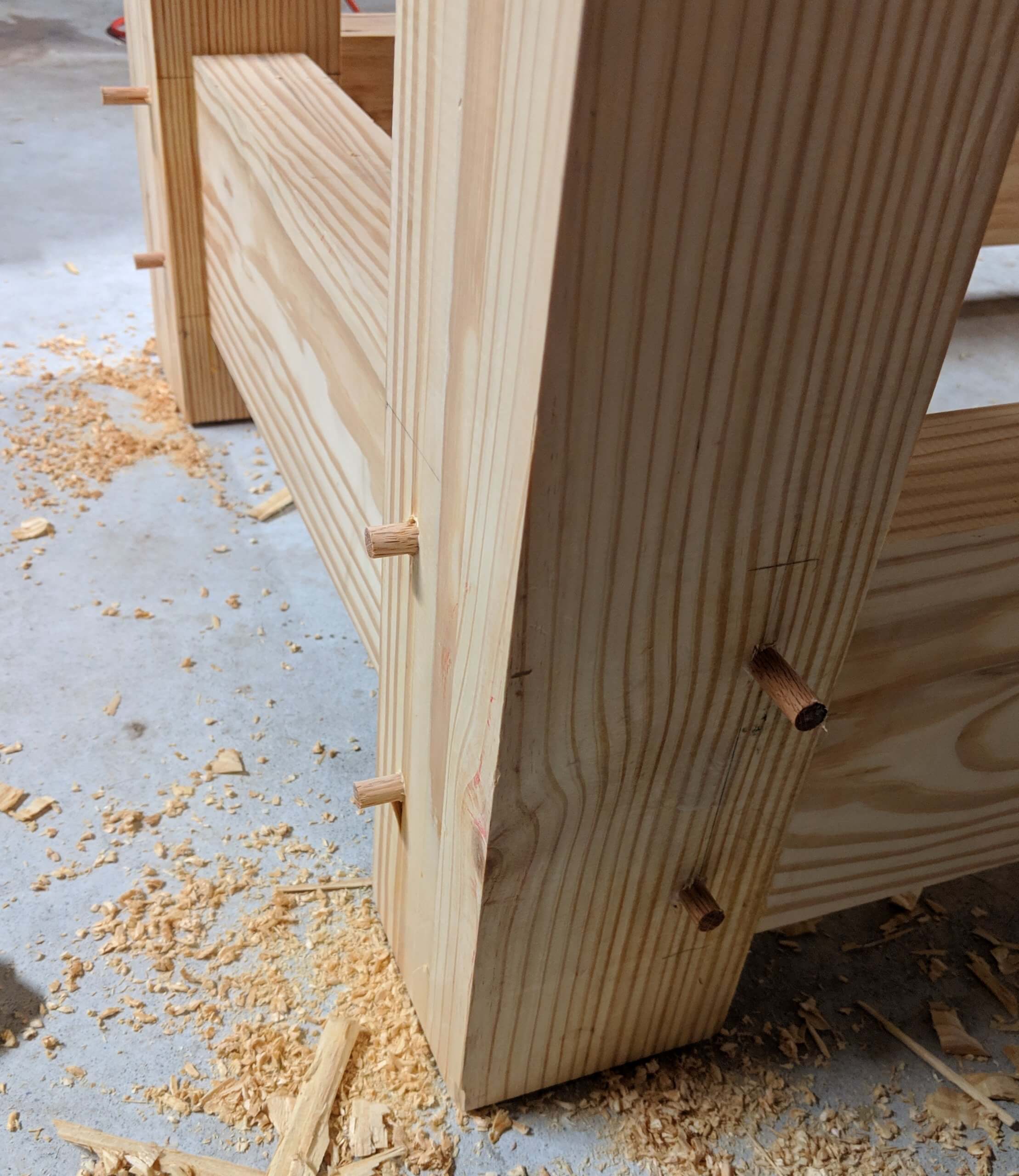
Though it is likely redundant given the massive timbers used, I drilled 3/8″ holes at the tenon location and pegged them with oak dowels, including the top tenons. Thus far the entire bench has no hardware and the dowels will give it added strength as I will be sliding it around form time to time. Once dry the dowels were sawed off flush and trimmed with a sharp chisel.
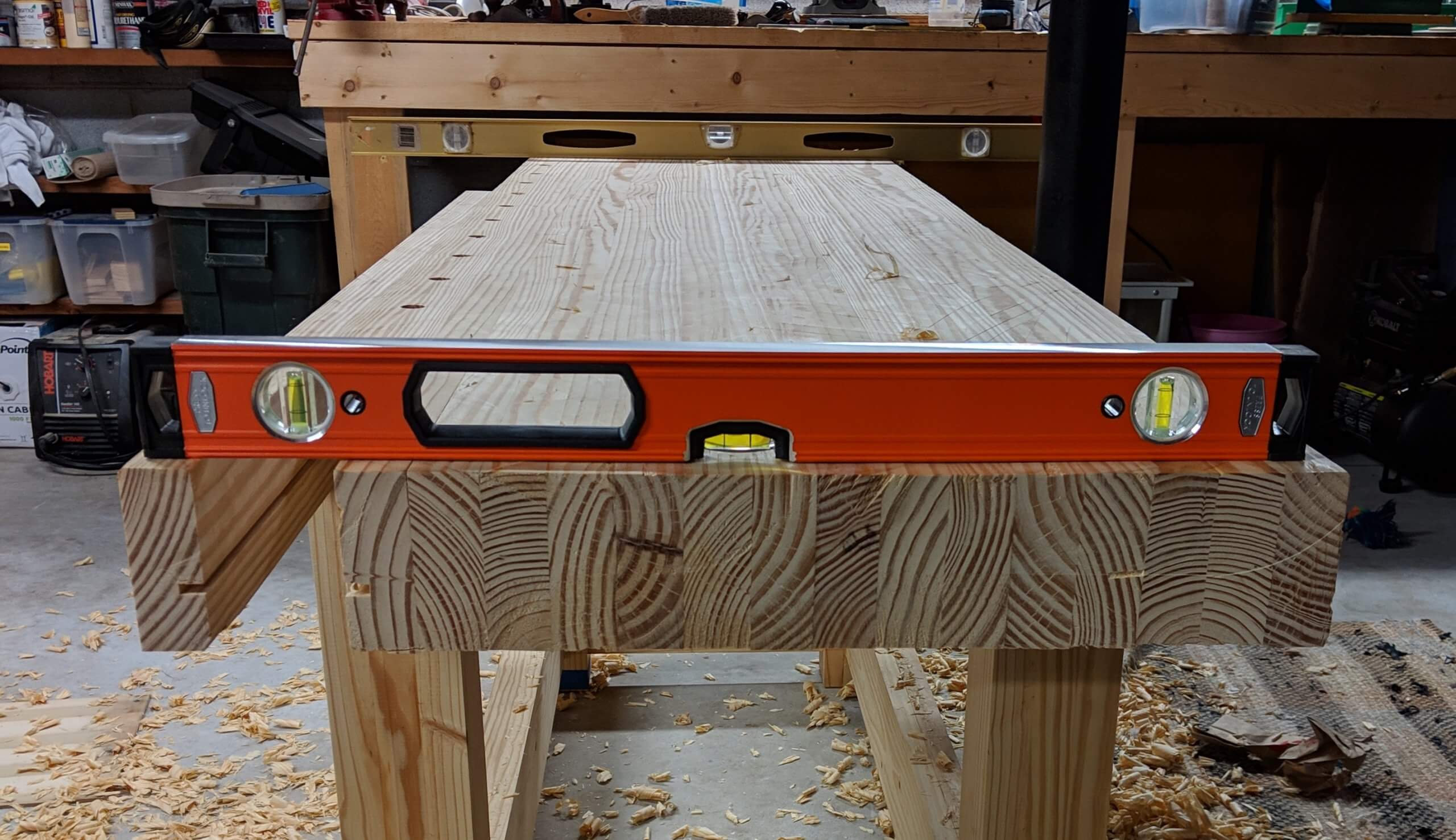
Flattening the Workbench Top
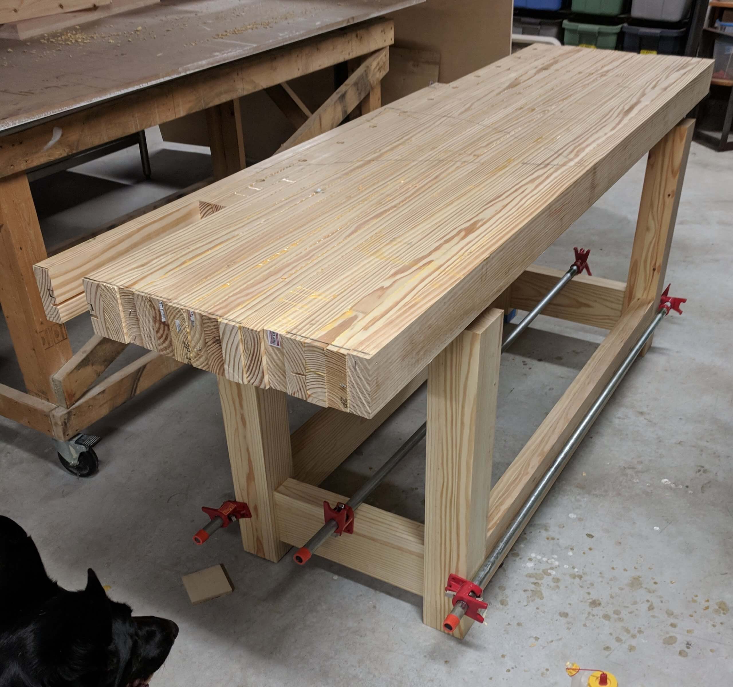
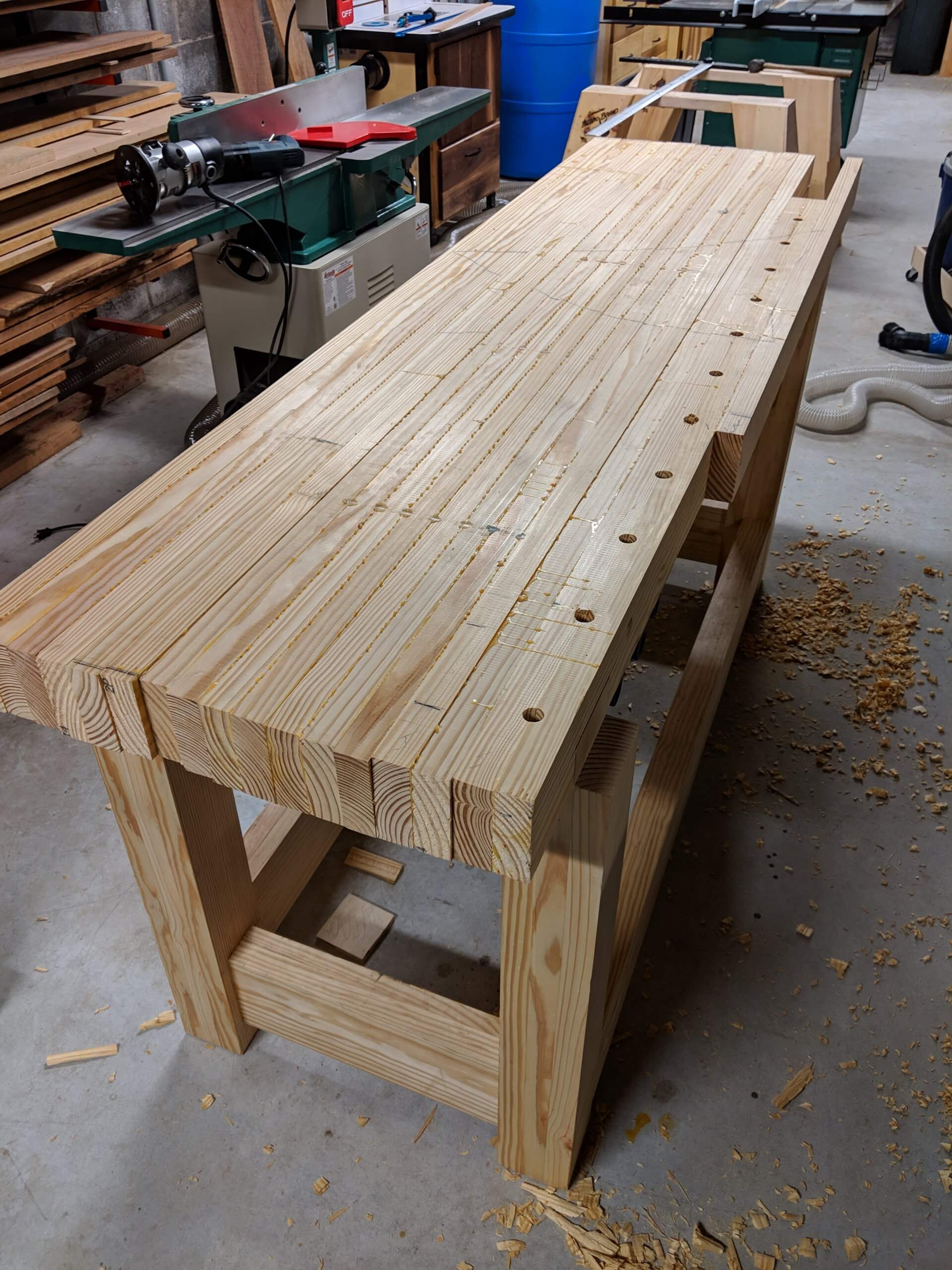
I moved the bench to its intended location so it would sit on the floor it would live on and checked the top with makeshift winding sticks (just two levels – note I am not checking level here, just using them as straight edges). If the top is in a single plane, you should be able to sight down the top of one stick and it will be parallel to the other. In my case the bench had a slight twist, with the left rear corner being about 1/8″ high. I moved the left stick in in increments to see at what point this disappeared and marked the top.
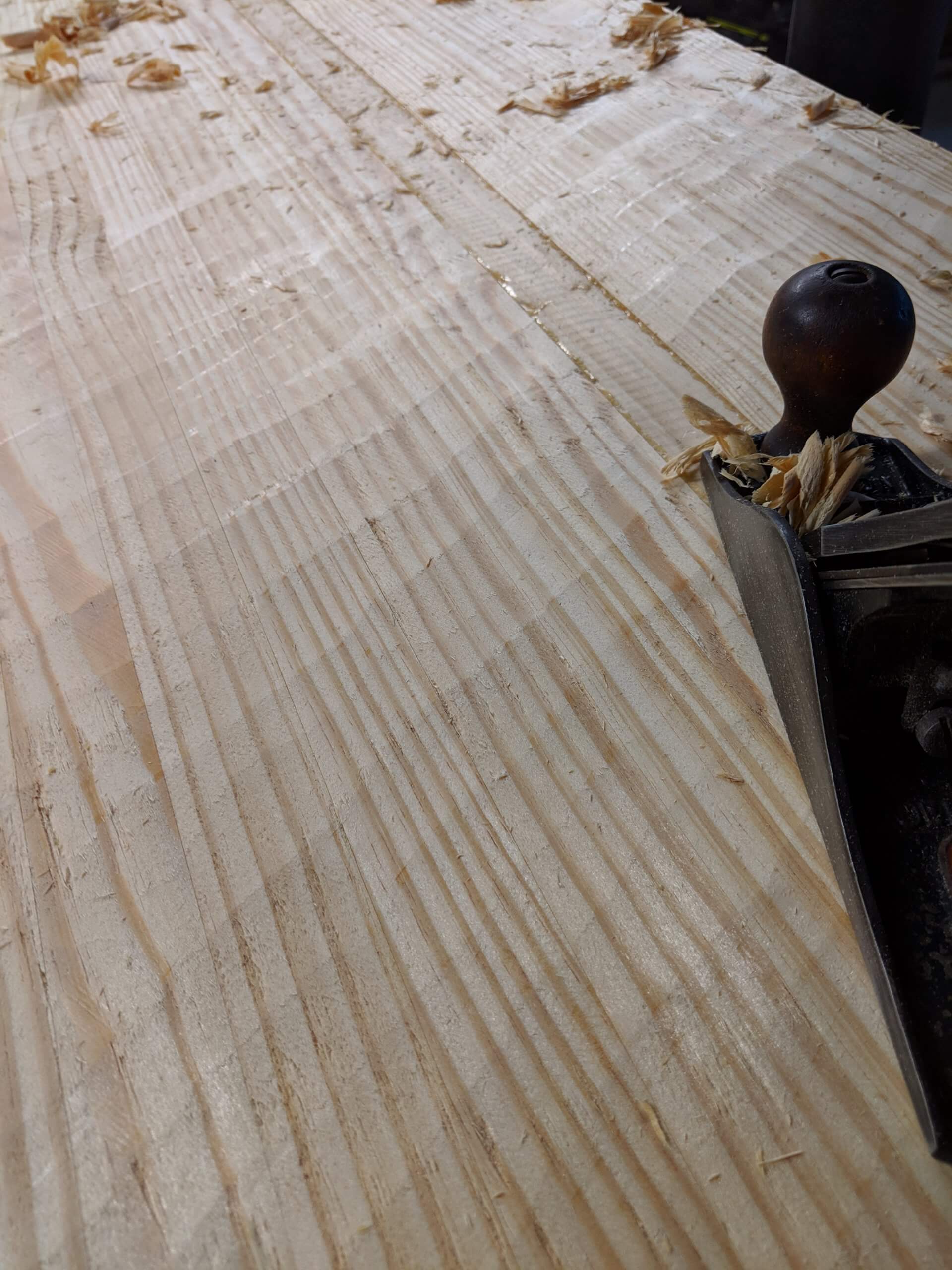
There are a number of tutorials on how to flatten a bench or table top online and I won’t bore you with too much detail. The first step was to have an understanding of the plane the top was in using the sticks above. The second was to rough out the top with a scrub plane. This is nothing more than an old #4 that has had the blade curved and the mouth opened so it can take big big bites. You can see the scalloped texture it leaves as you work cross grain. you can also see how I have to work down to the lowest board in the top. Once the scrub plane reached the lowest board, it was time to tackle the slight warp. Using the scrub plane made short work of knocking off the 1/8″ rise in the back left corner and frequent checking with the makeshift winding sticks showed the bench was true, but not flat.
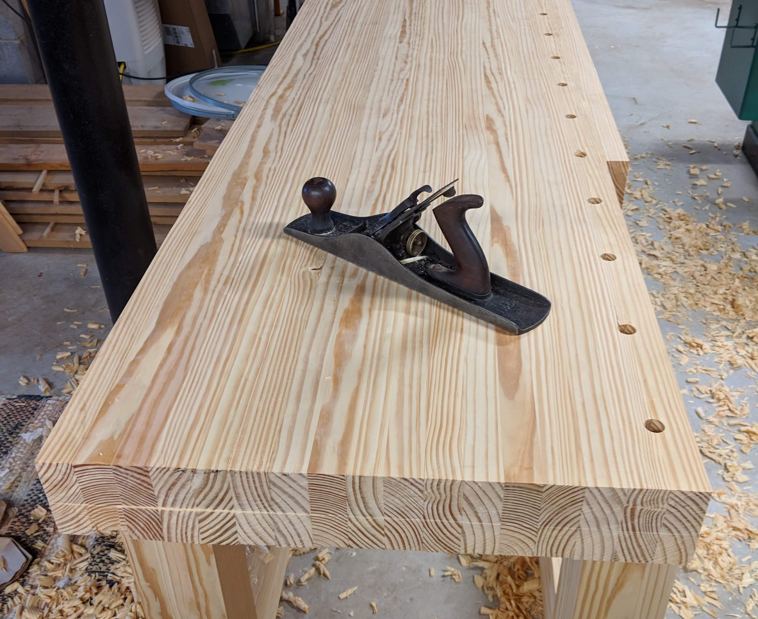
After the scrub plane came diagonal passes with a jack plane. The reversing diagonal (left to right the right to left) back and forth method took out the high spots left by the scrub plan.
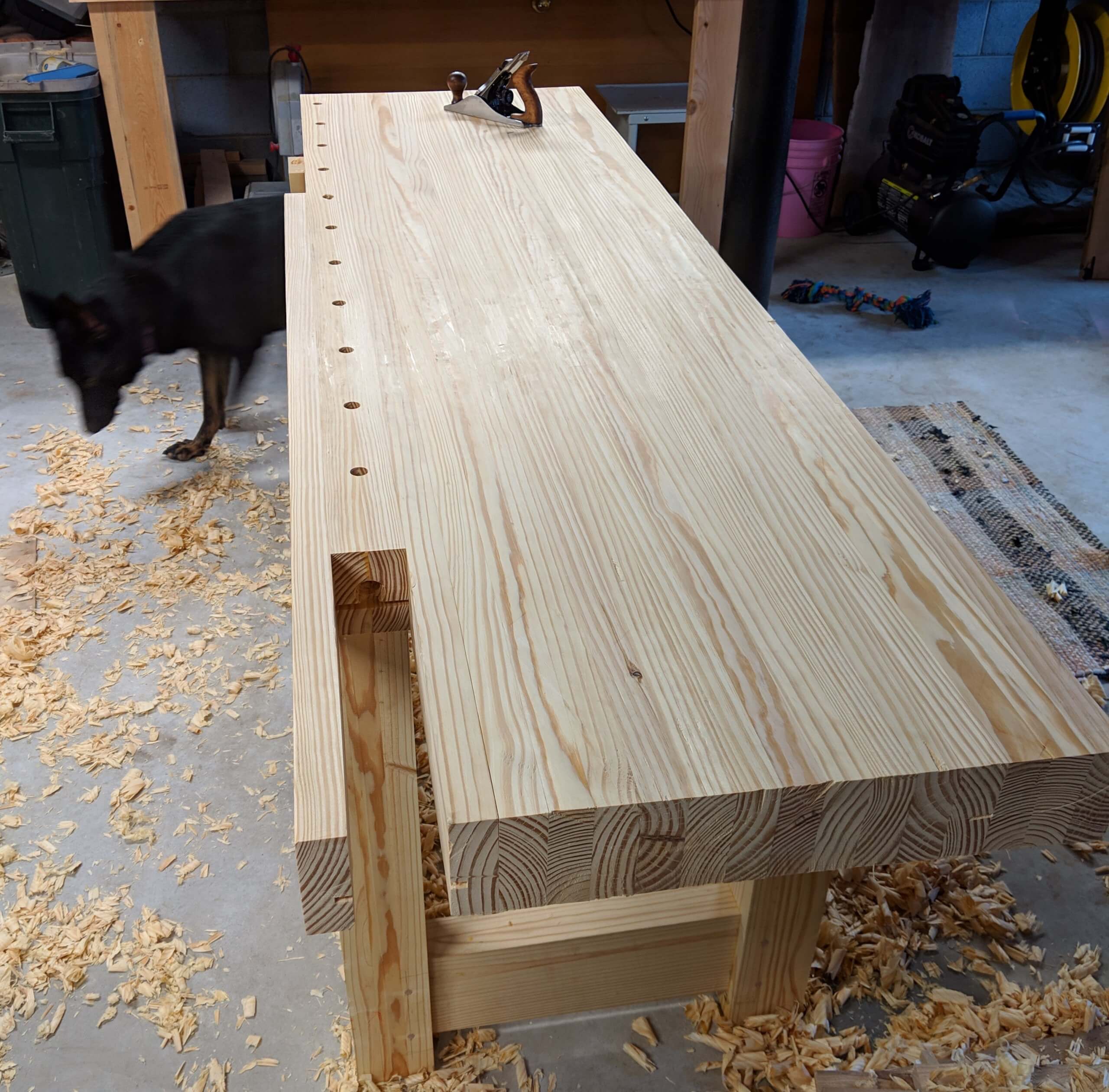
After the jack plane comes the #4 smoothing plan, again with diagonal passes, then to passes with the grain while the plane set to a very light cut simply to take off the remaining tool marks. In the end it took 16 passes with all the planes and a total of about 1/4″ was taken off. The last plane was called Ibuprofen.
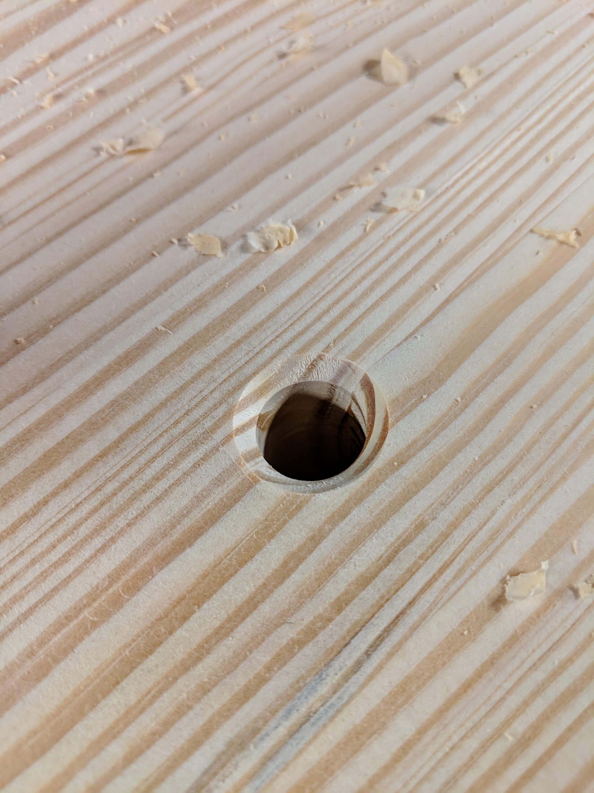
With the top flat, I chamfered the dog holes to make inserting them easier and to discourage tear out during use.
Front Vise
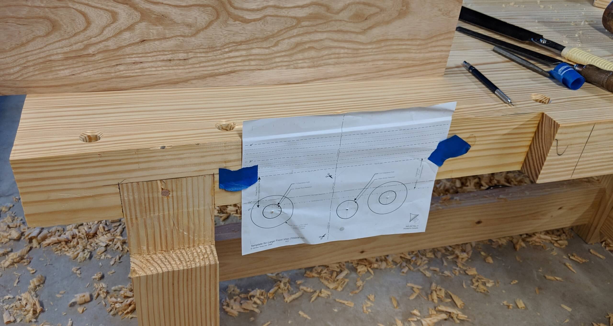
I taped the vise chop template to the bench face where it lined up with the already mounted vise mount. This was much better than trying to measure or “get it right” from pure math.
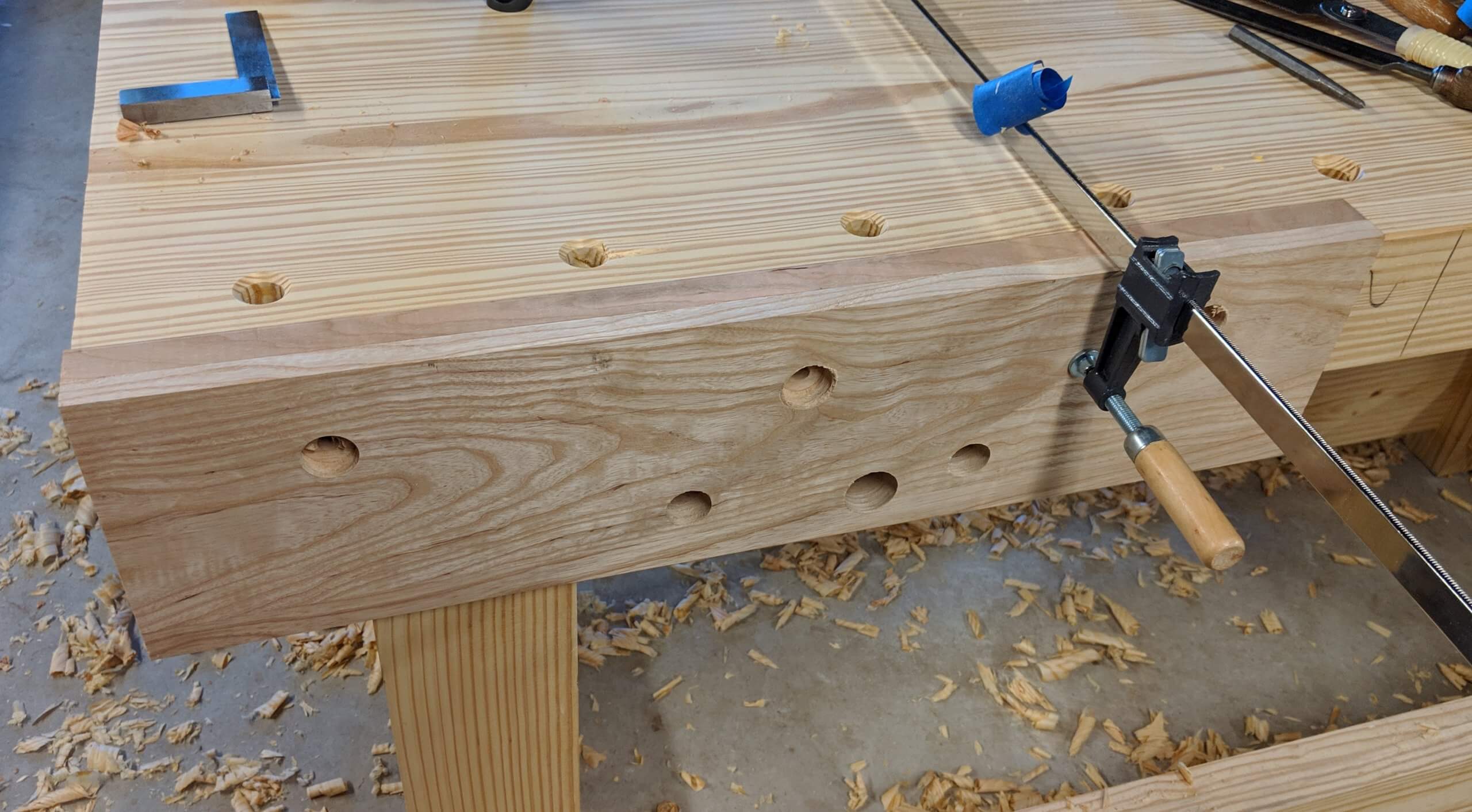
I put the bench-side chop in place and folded the paper over and taped it so the location of the hole centers could be transferred to it. I then clamped the inner and outer chop together and drilled them as one unit. I added three recessed holes for lag bolts on the bench-side chop. I contemplated gluing it on but decided I wanted to be able to replace it in the future.
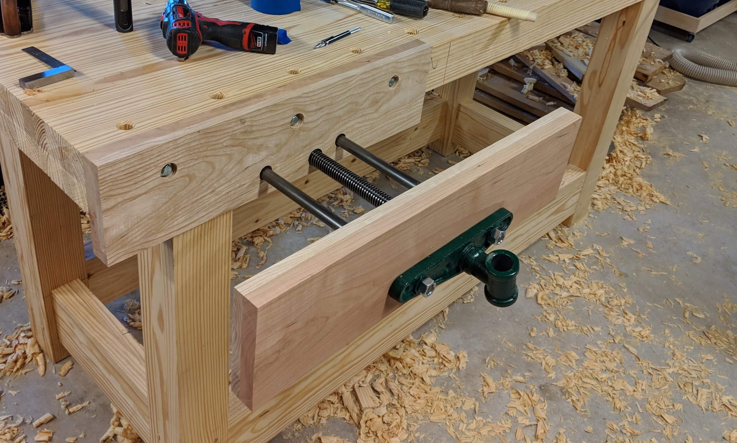
I threaded the vise screw into the base and through the front and back chop to locate the back chop perfectly for mounting. I drilled pilot holes for the lag bolts and secured the chop firmly with 1/16 sticking above the bench top so it could be planned perfectly flat. The vise was then closed and the front chop positioned square with the back chop, then mounted with screws set into pilot holes.
Some will say the chops are too long and they do in fact exceed the recommended maximum width from Veritas by about 4″. Yes, if the far ends are used the vise will rack, but I intend to use the center mostly and will use blocks to prevent the racking if needed. In the end I wanted a large surface for dovetailing drawer sides and will make it work. You can build yours however you want. In testing with a modest block on the opposite side the vise holds amazingly well at the extremes and will work perfectly.
Some will also notice that this is not a “quick release” vise. Two things. One the budget was $250, so you get what you get and two, when I am in the shop I am more interested in quality than speed, and a quick release vise, though great, isn’t needed for me as I don’t need to “hurry up” and relax. It is a solid vise and a few extra turns of the handle may one day cause me to avoid a mistake or have a really great idea as I ponder what cut I am about to make.
Wagon Vise / Tail Vise
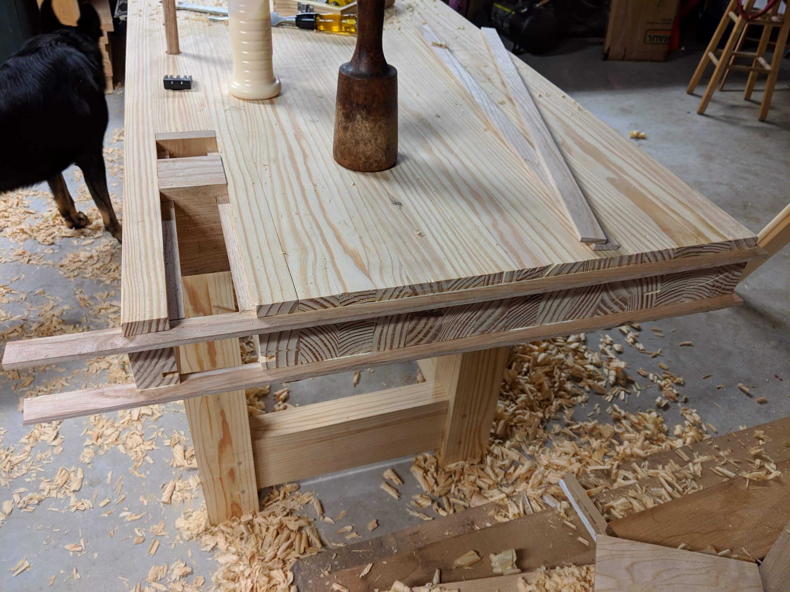
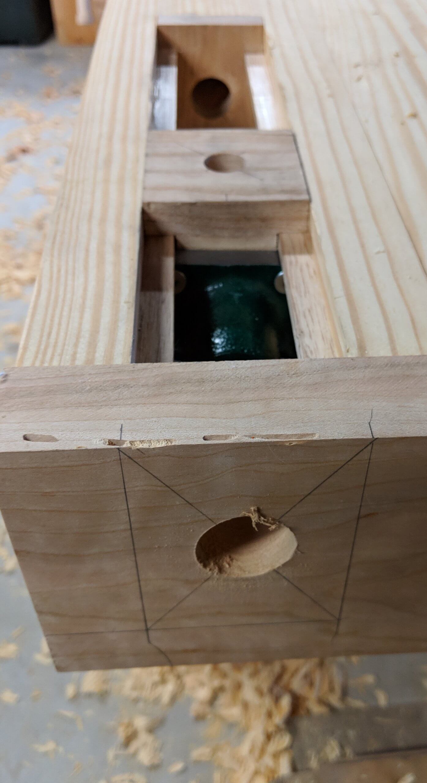
There are several things shown in this image, just to simplify the descriptions. First a block of ash was made that fit into the wagon vise slot. A second block of ash was made to fit the end of the wagon vise slot to act as a bushing for the end of the screw. It was drilled to fit the screw and mounted with glue. Two slots (on each side, four total) were cut into the sides of the wagon vise channel and ash runners were glued into the top slots, with matching slots cut into the sliding ash block.
So here is the block after working it up. It has slots that fit the rails in the wagon vise channel and it has runners that fit into the other set of slots in the channel. A dog hole has been drilled on the top and a through hole has been drilled to allow the screw to pass through. Finally, the location of the hardware that threads onto the screw has been established with holes pre-drilled.
Identical slots were cut into the top edge for the apron that would hold the wagon vise screw handle. These were glued in and the area for the block was cut out. This creates a simple spline joint for the apron.
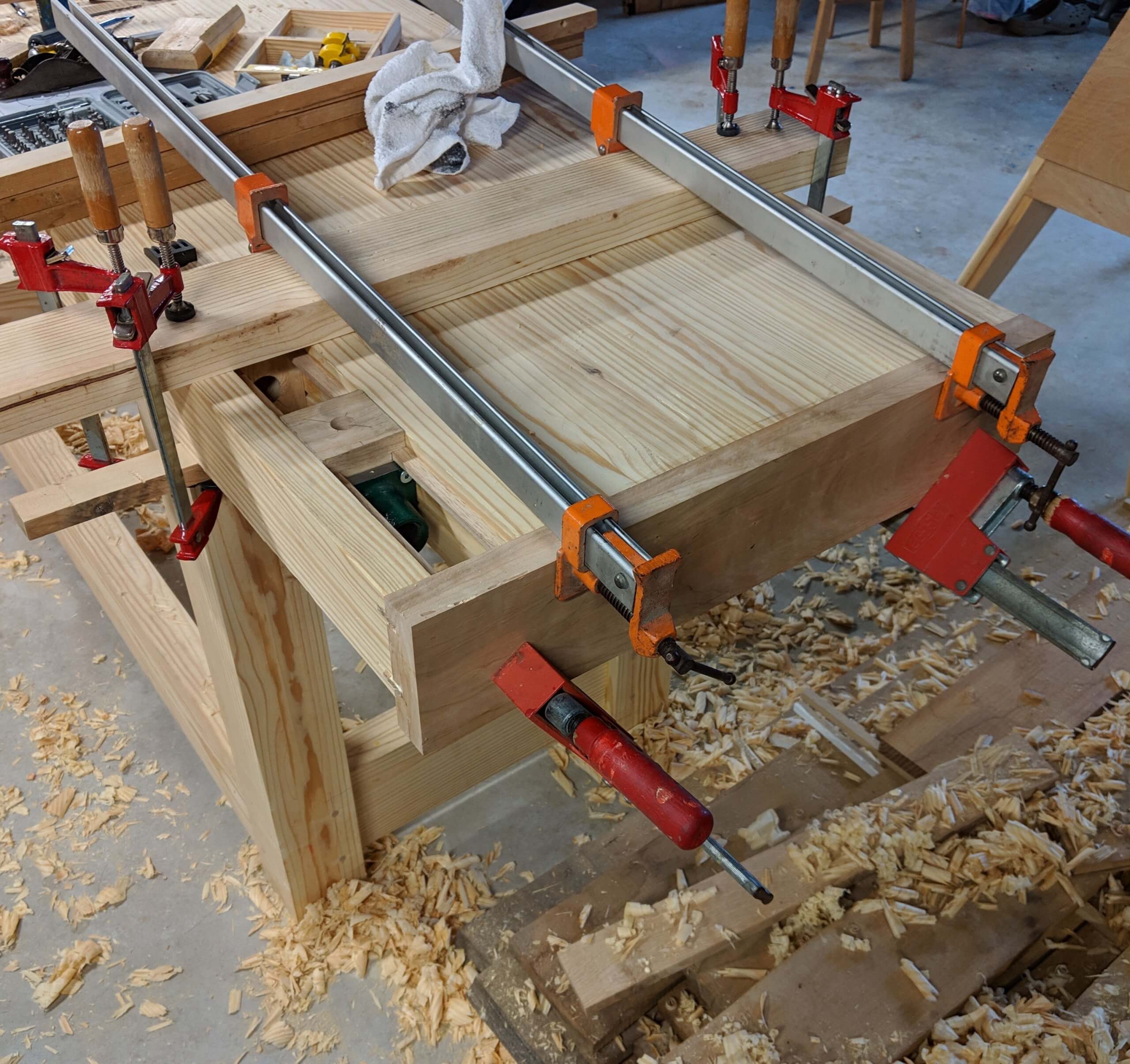
The “bolt” for lack of a better word was attached to the sliding ash block and the entire assembly was coated in wax. Once installed, it would not be free again without taking off the apron. It moved free and worked well. Matching slots were milled into the cherry apron and it was glued on with cauls holding the clamps from moving.
With the apron dry, the location of the through hole for the screw was marked and drilled. I will point out that Veritas intends the head/bolt for the block to be mounted inside the block. I did the reverse as an internal mounting would have conflicted with the dog hole. To correct that would have required a longer block and that would have been about the same size as just mounting it the way I did. There are no instructions with this unit and you generally have to make what works for your situation. “If” I ever take off the apron and fiddle with it, I will have a smaller head machined or at least take 1/2″ off of this one.
The screw and mount were threaded onto the block and into the bushing, then the location for the mounting holes were marked and drilled.
When I mentioned that I might do this differently I am referring to the alignment. The three points of contact have to be in a perfect line (apron hole, block hole and busing hole). My bushing hole is slightly high and causes the block to get harder to move as it approaches the end of its travel. This is an area that I don’t expect to use often, but will be taking the hardware out and using a very long chisel to remove some of the bottom portion of the hole. A better solution would have been to make each hole 1/8″ larger to allow for normal assembly variation. Either way, it works and gets easier as it is used.
Finishing Steps
I used a #4 plane to level the apron and the two chops with the bench top. I hit the top with 120 grit paper then 220. The entire bench received two coats of Osmo Hardwax Oil. This is hands down the best finish I have found. It is a perfect mix of penetrating and film forming finishes and is intended as a floor finish so it is tough. It goes on by hand rubbing and is as easy to apply as boiled linseed oil.
Do you have cut plans for this bench? Or any plans for it?
I more or less had basic dimensions in mind so I just cut as I went. If you want more specifics, email me and I will help you along.
Nice work and a good read as well. I have been thinking way too much for too long about my bench build, and I am finally close to starting. My build will be very similar to yours, lumber and wagon vice, only difference will be a leg vice on mine. Thanks for sharing.
Thanks. You should see the bench now! It is tired and beat, but still strong and true. Many many furniture items have been hammered out on it. I am glad I built it sooner rather than later.