
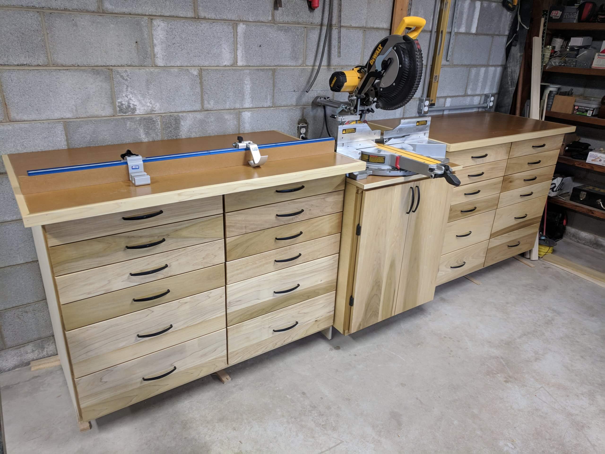
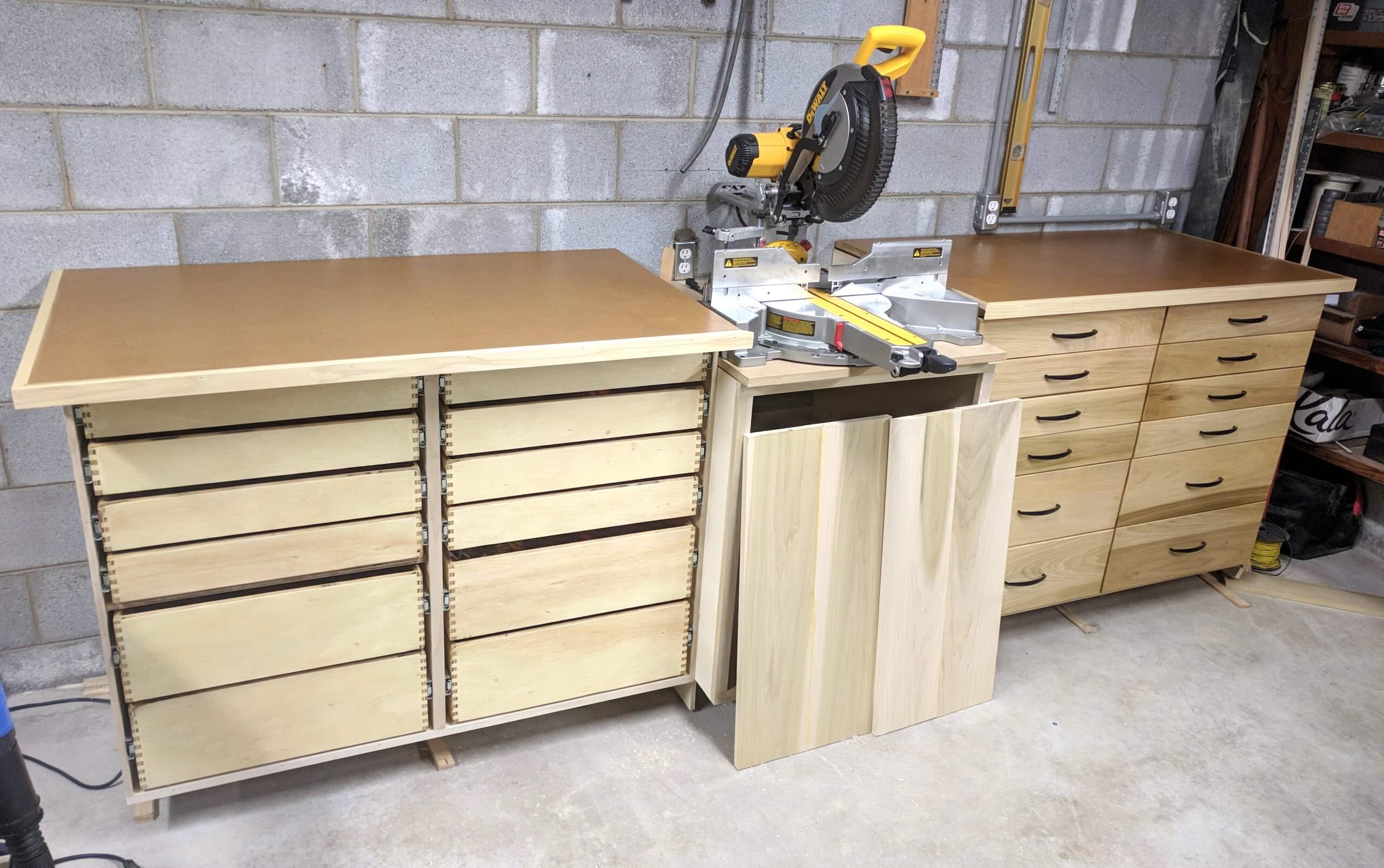
Miter Saw Bench with Storage
For some time I have needed a better miter saw station and additional storage in the shop. To accomplish each of these I designed a simple materials efficient set of cabinets to work in conjunction with the miter saw. Since many of you are new to cabinet making and most “how to” articles these days are on YouTube, I am documenting the build so you can see some of the details. Fair warning, this is a bit long and some of it may be “old info” for you. If so, skip ahead.
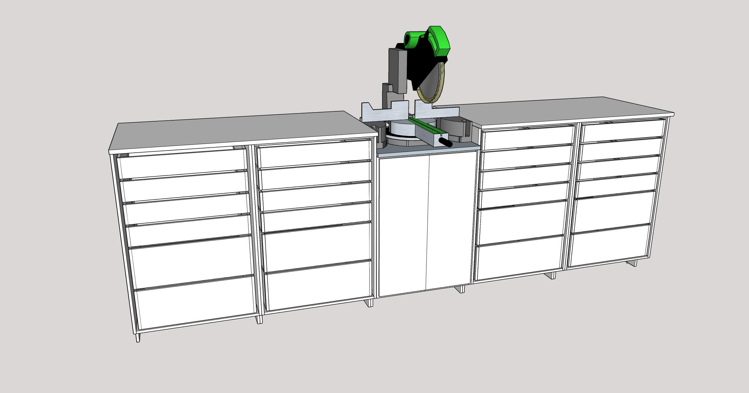
Disclaimers and Notes: The depth of the cabinet is 23 7/8th inches so that two sides can be cut from the width of a standard sheet of plywood. My cabinets are made exclusively (other than the facia) from 1/2″ cabinet grade plywood. Structurally they require a counter top and wall mounting as a back and top are omitted. They are not designed to be freestanding structurally, but could be if you installed a full back versus the stringers that are standard for wall mounting. Free standing cabinets should also be made out of 3/4″ plywood. To optimize storage, they are made in the European style, in that they lack face frames. The SketchUp model includes cut sheets for the left and right cabinets, but not the center as this will need to be sized to your saw (how far the support cabinets are from each other and how low the saw sits relative to the counter top).
The SketchUp model contains sheet layouts. The first six sheets are 1/2″ and the lower three are 1/4″ for drawer bottoms.
The assembly is in five parts, carcass, drawers, saw cabinet, installation and fence.
Carcass
In cabinet speak, the box that holds the drawers or openings for the doors is a carcass. It is generally just a box with supports for drawers or shelves. Its real job is to be square and the right size.
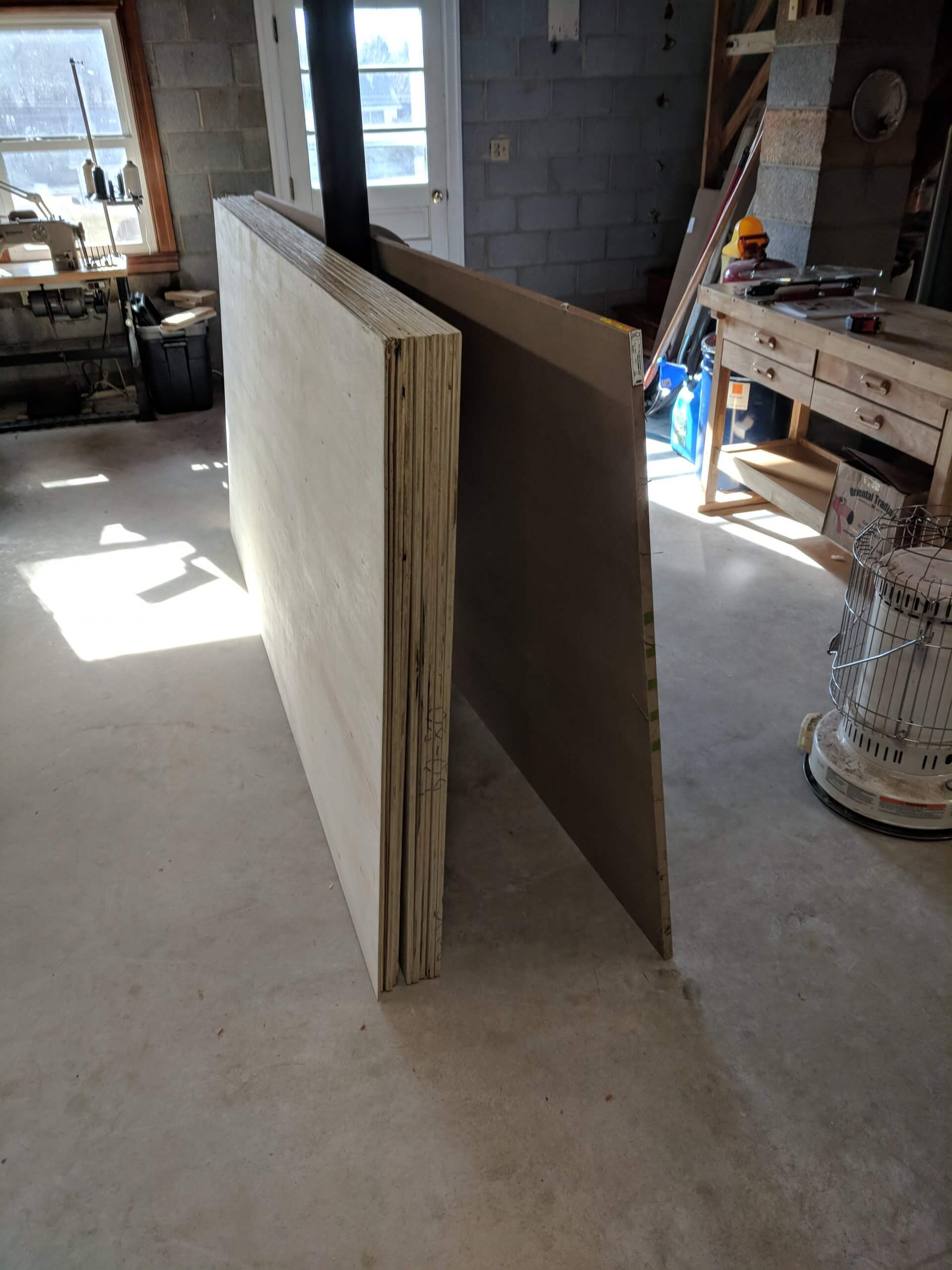
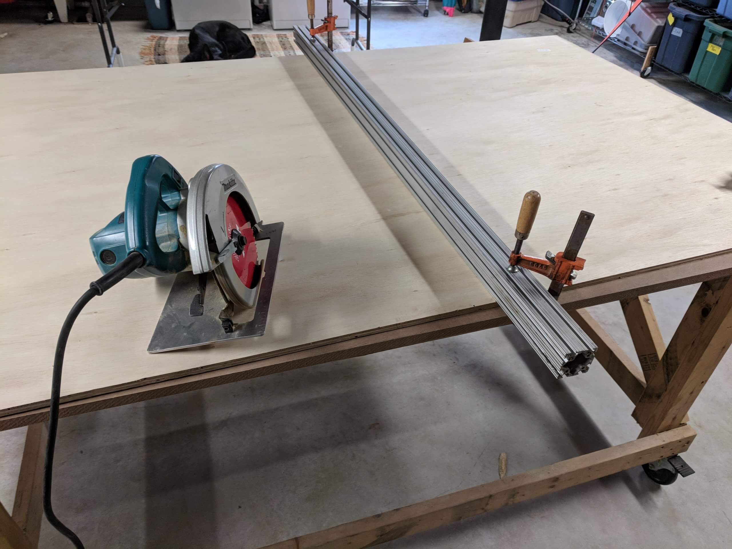
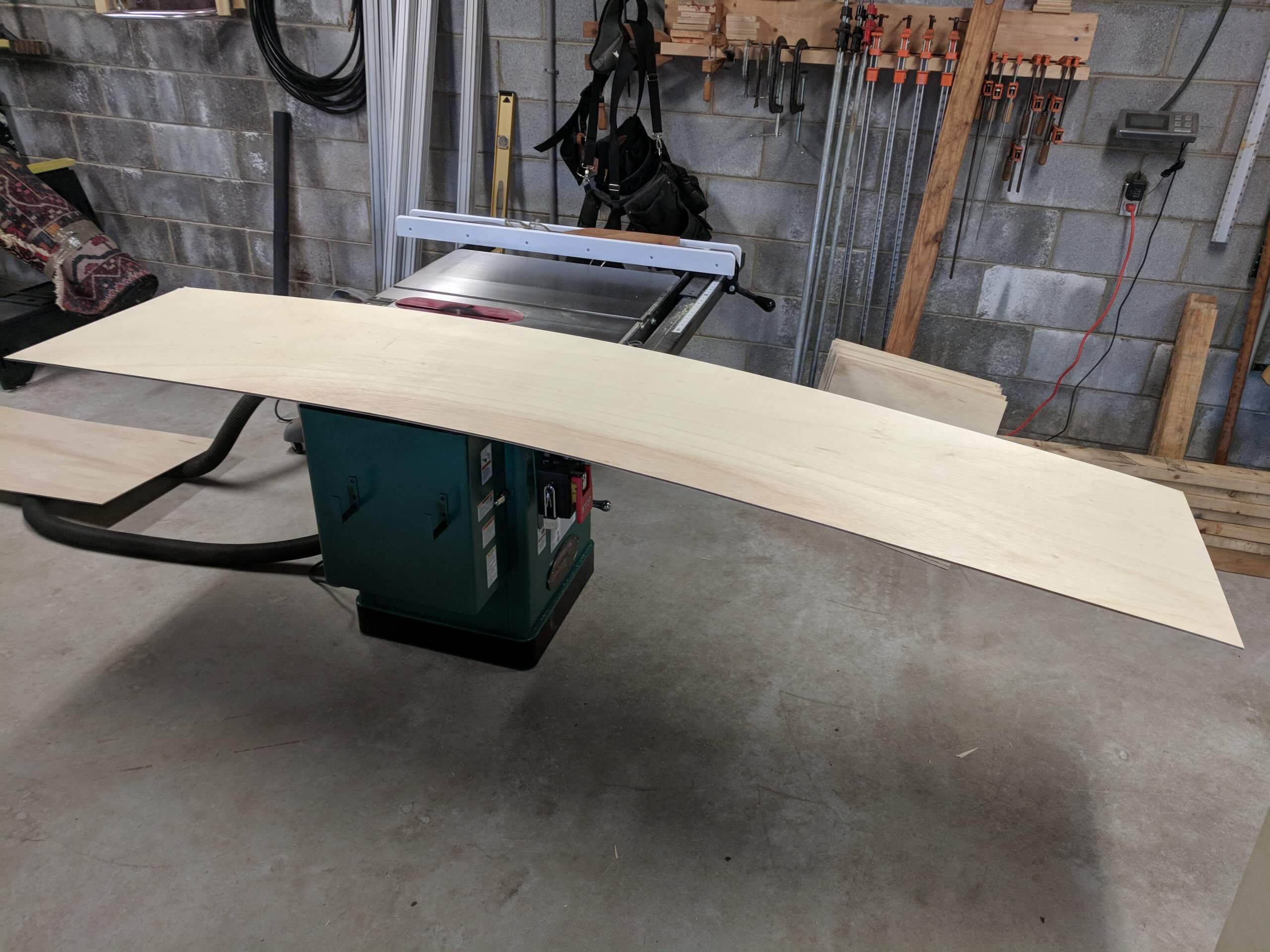
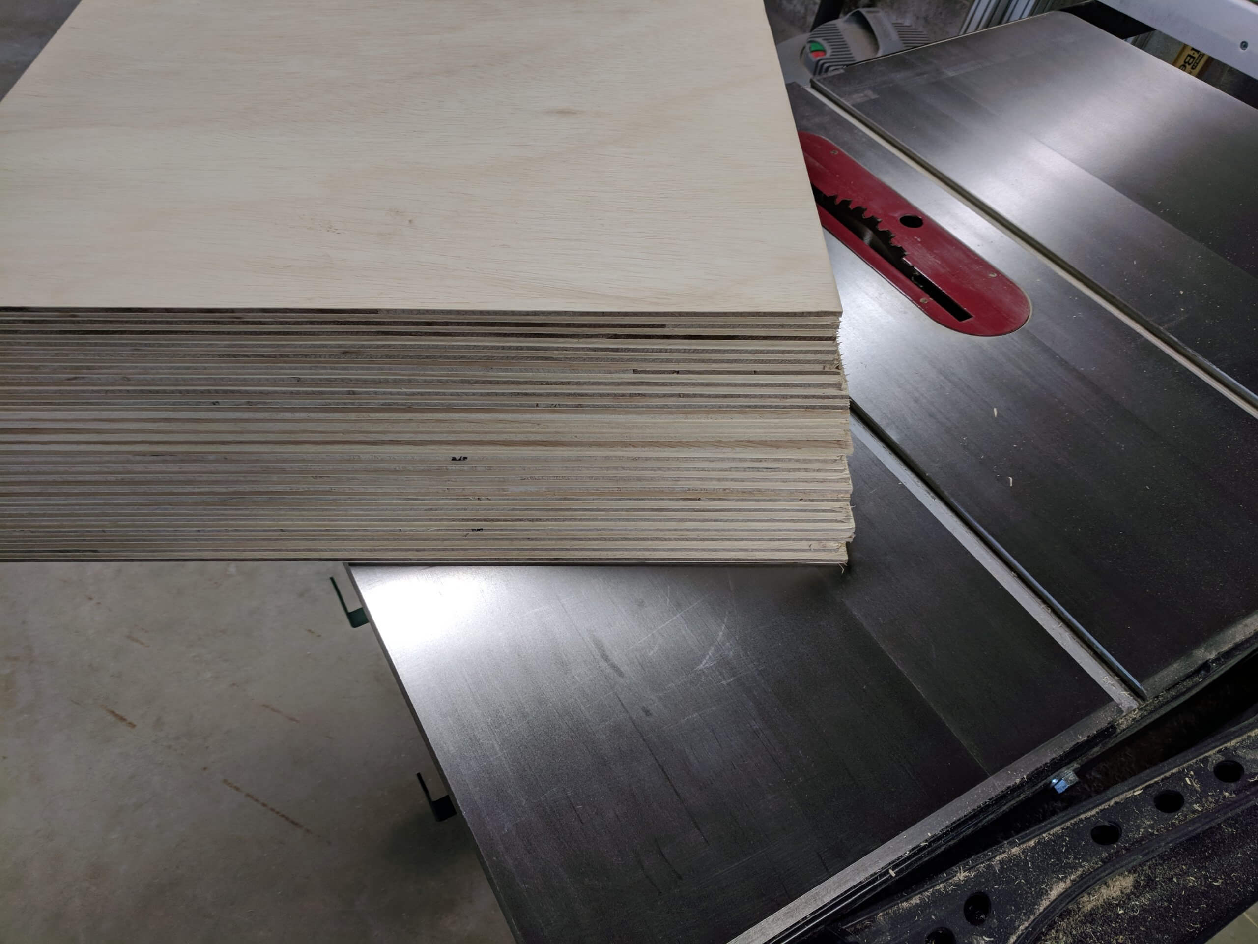
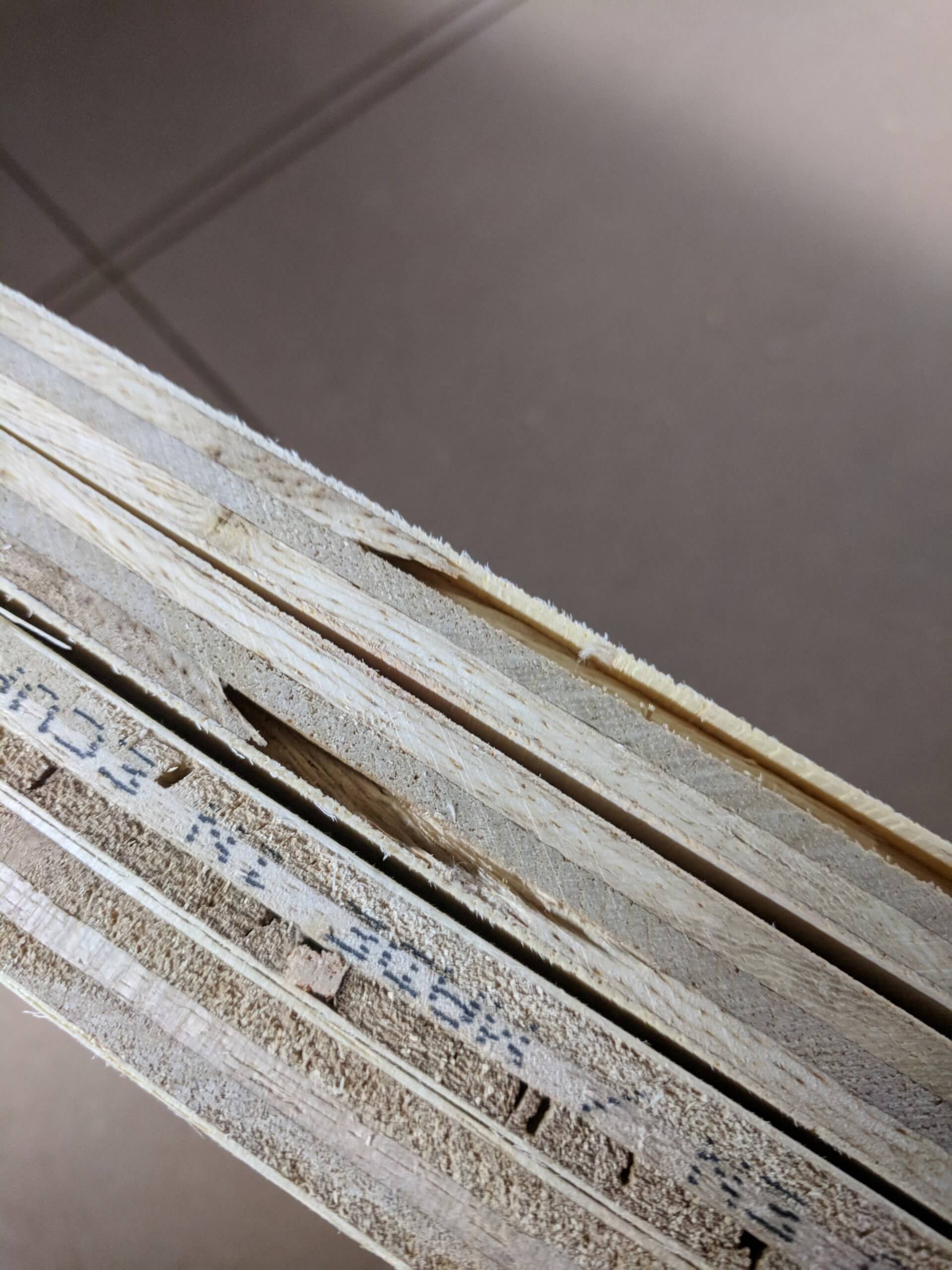
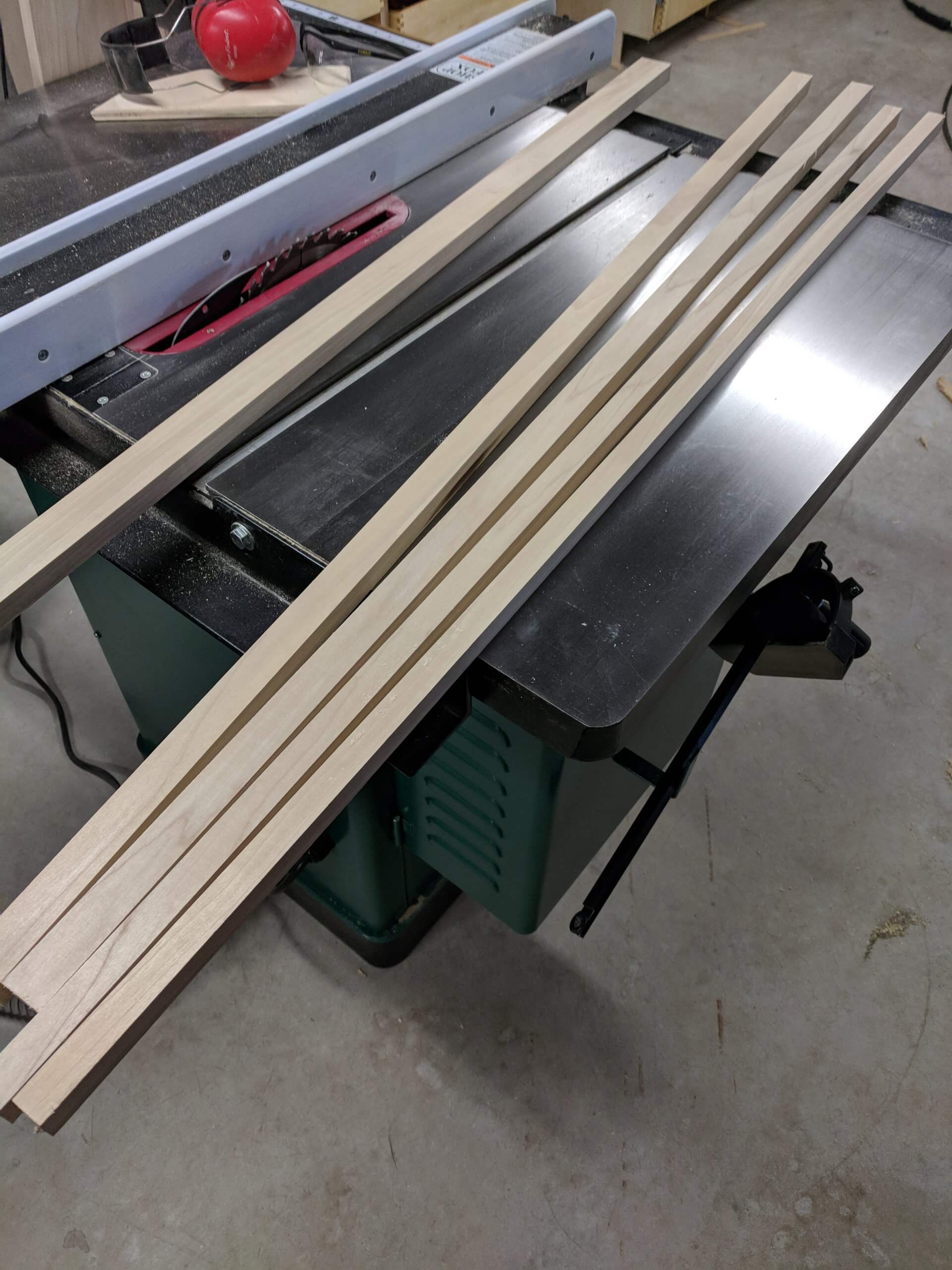
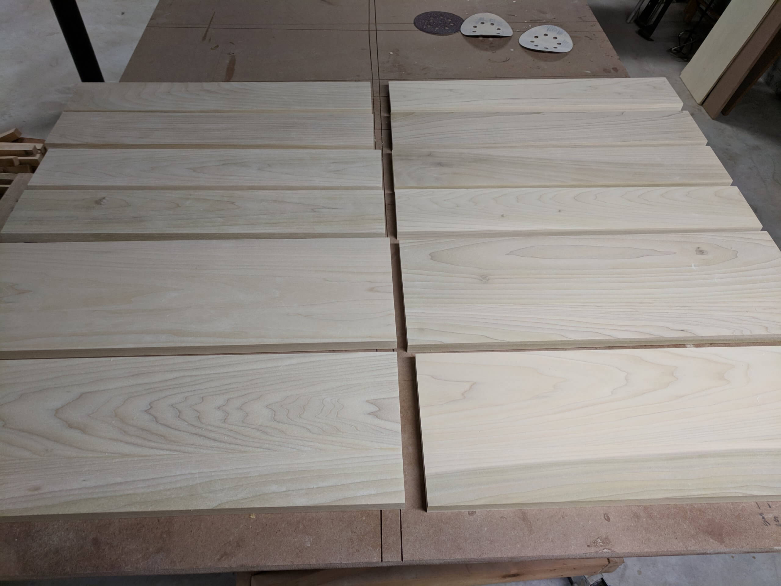
The first step is to cut the whole sheets into rough-cut sizes that can be managed at the table saw. It is very hard and not all that safe to try and make finished cuts from whole sheets. Cutting out parts with at least two “factory” edges and a 1/8″ to 1/2″ margin allows for clean cuts on the table saw.
The four base units are comprised of eight sides 23 7/8″X39″, 12 stringers that are 6″X23″ and four bottoms that are 23 7/8″X23″. No dimension exceeds the size of half a sheet in width so parts can be stacked cleanly. Other than plywood, three 1/2″X6″ cleats and one 1/2″X19 7/8″ cleat are used per base unit to give the 1/2 plywood stringers and bottom a better mounting surface.
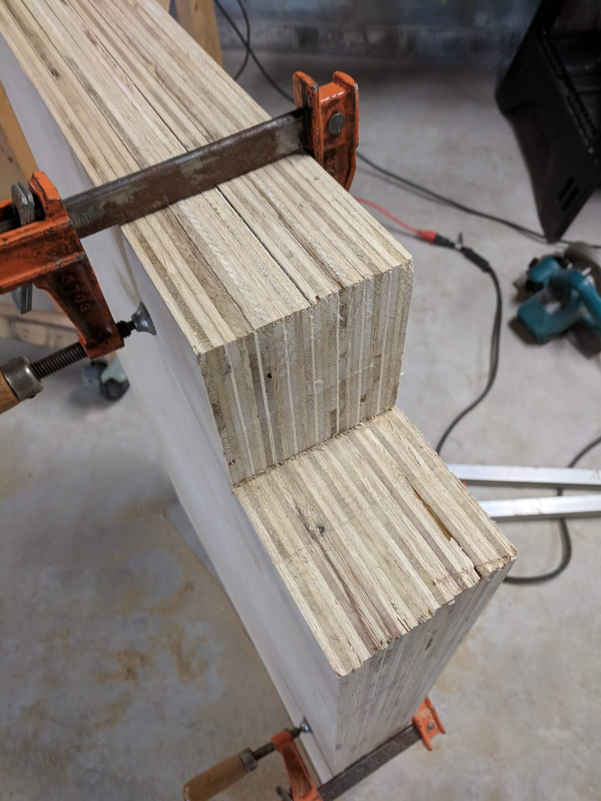
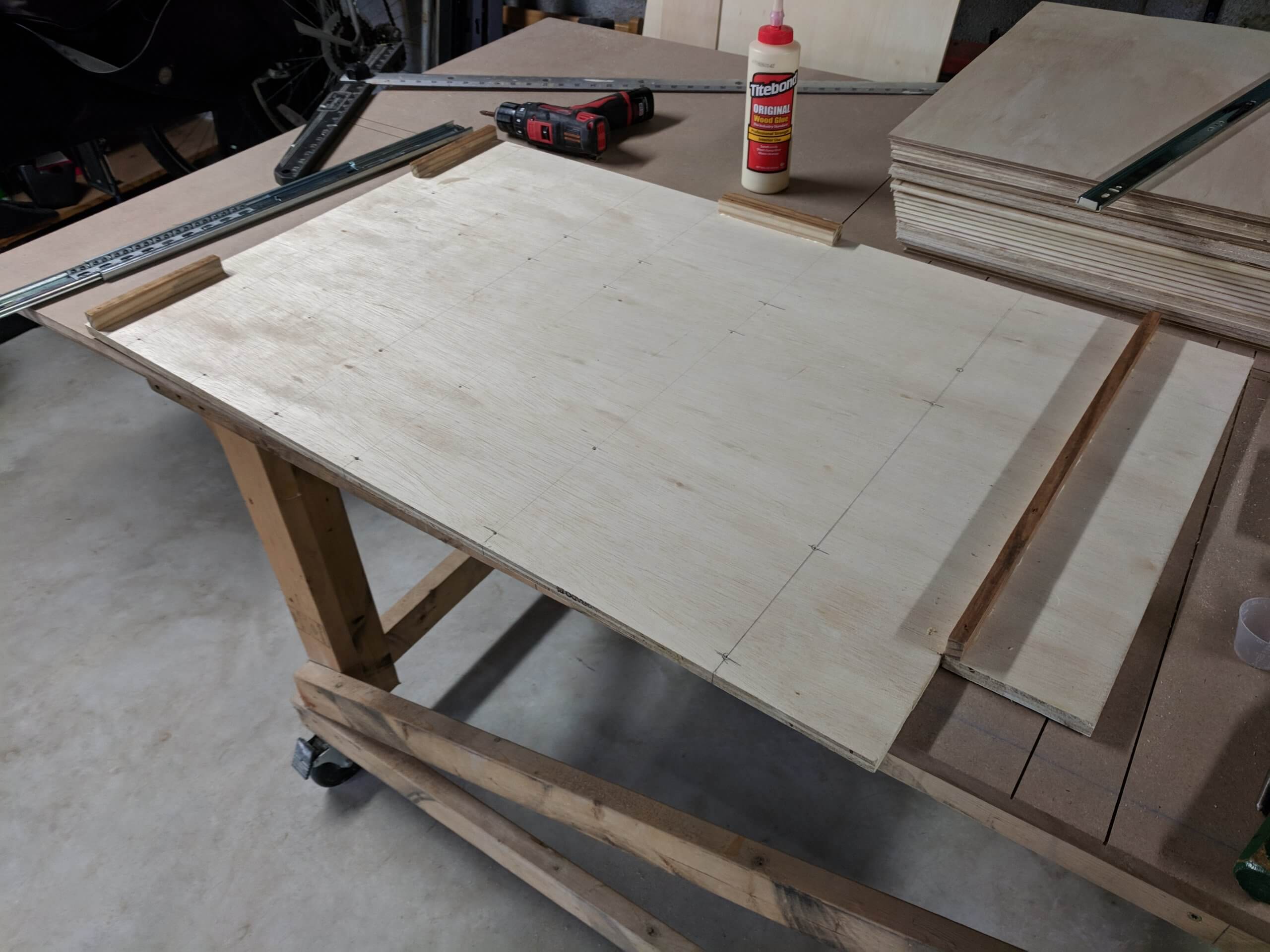
With the sides cut to the final shape, they can be clamped together for marking all the drawer slide locations as well as the cutout for the toe kick. The toe kick can be cut out at this stage using a circular saw. I use a 4″ toe kick and you can adjust yours up or down, but if you make it larger you will need to alter the size of the bottom drawer.
The bottom drawers are 7 7/8″ tall and the top drawers are 3 3/4″ tall, each with a 1/2″ space between each drawer and the top stringers and bottom. Drawer slides will be installed on the center-line of the drawers so their location can be determined now. Using the model, the drawer center-lines are 8 11/19″, 17 1/16″, 23 3/8″, 27 5/8″, 31 7/8″ and 36 1/8″. Since all the sides are identical, the drawer slides will be installed before glue up to make assembly easy and square.
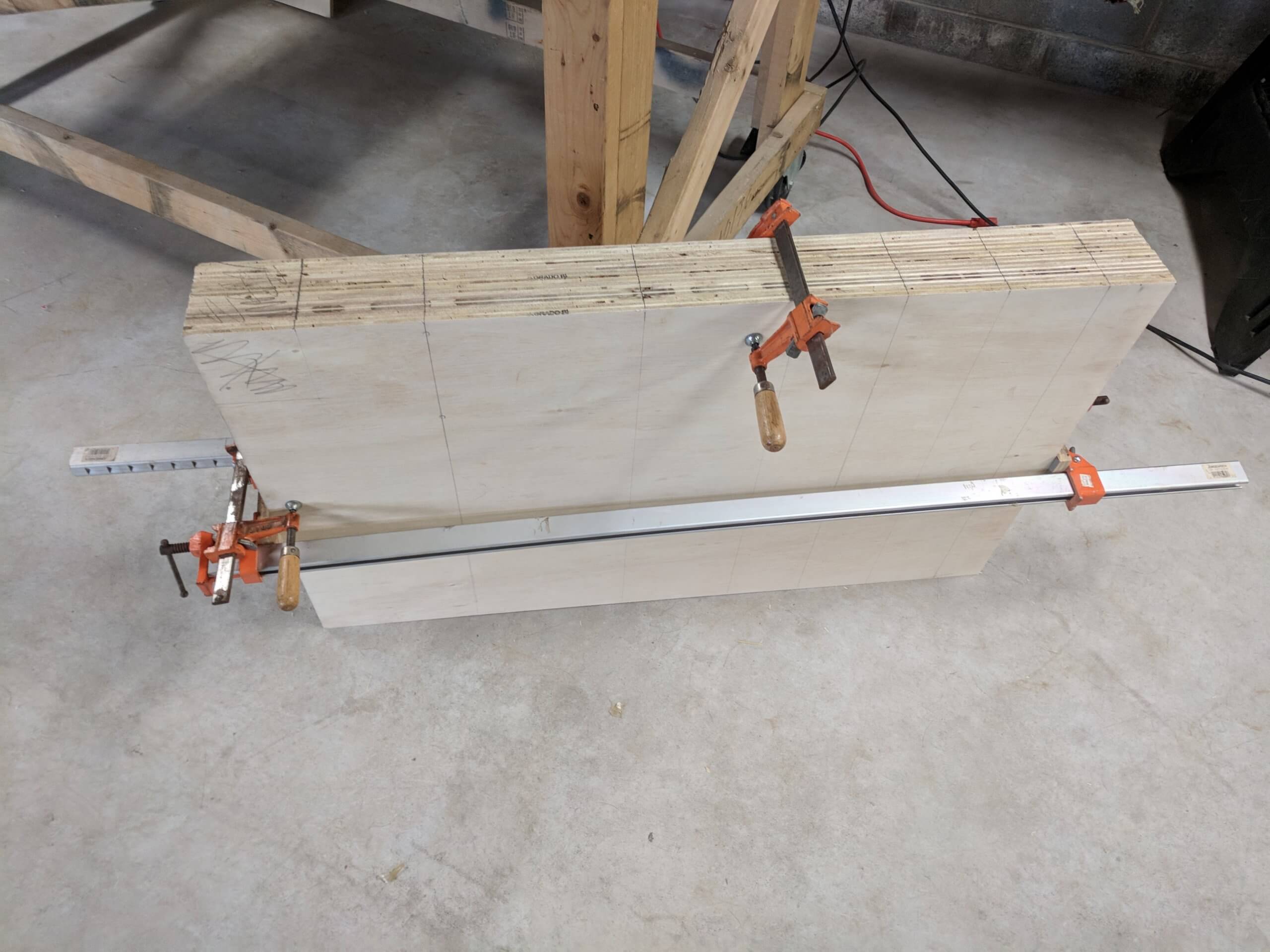
When clamping the sides for the toe kick cut, pay attention to keeping them perfectly aligned. Note the bar clamp in the image keeping them stacked together correctly.
Use a square to extend the drawer slide locations that were marked on the face of the plywood. At this point you should pair up your sides into groups of two so you mark inside faces.
1/2″ plywood lacks the thickness needed for joinery (you can’t cut a dado into it for mating right angles pieces). To give the stringers and bottom something to square up to, I used four cleats per side. These are 1/2″ stock placed at the bottom below the toe kick, the top at the front and back and in the center of the back. Be certain to align the center back cleat identically on all sides as you will use this to install the back stinger true and square.
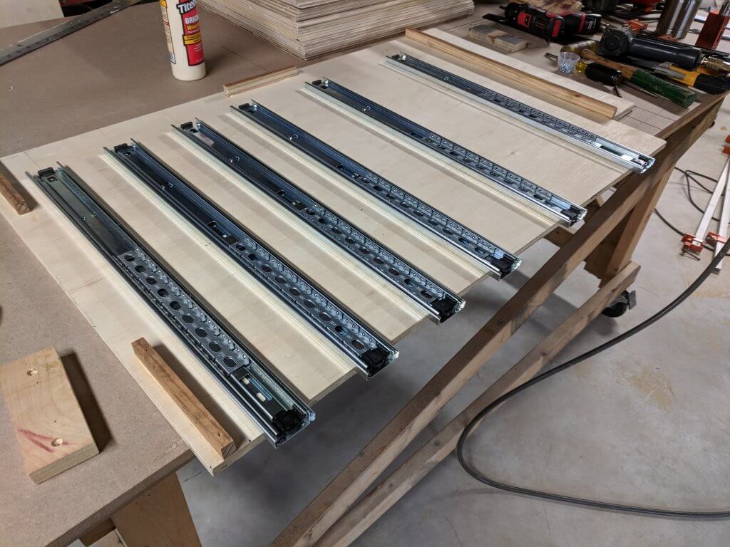
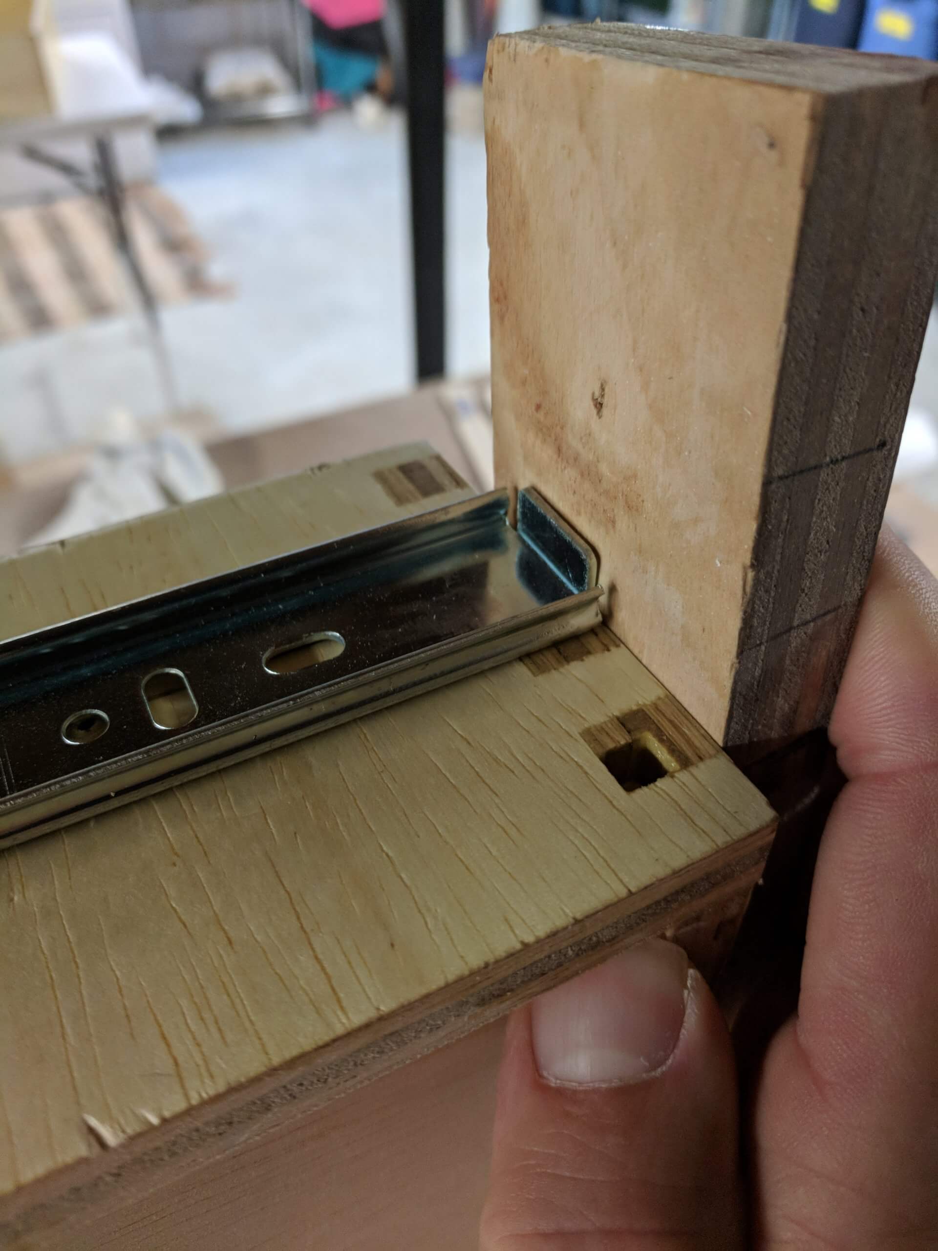
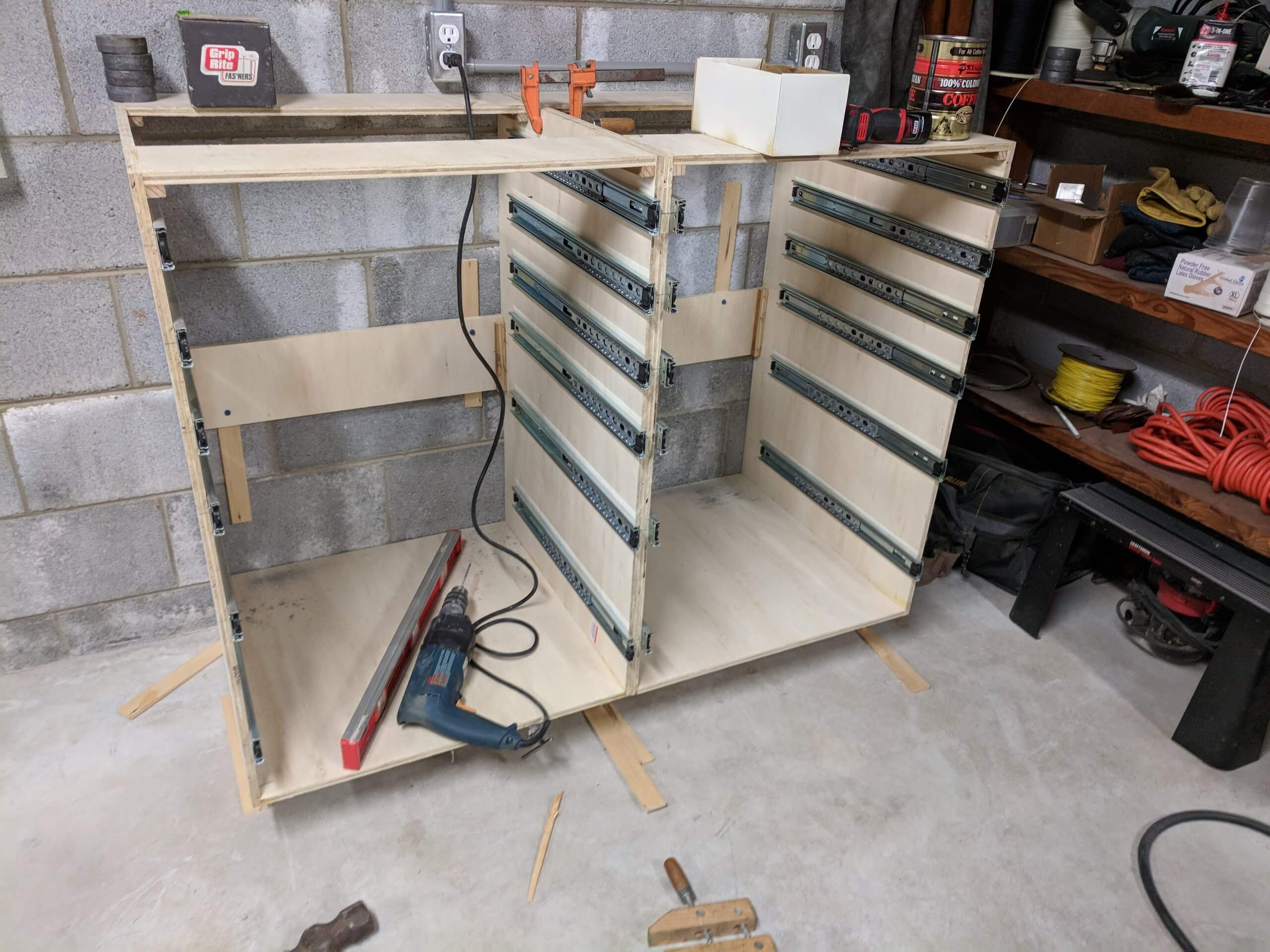
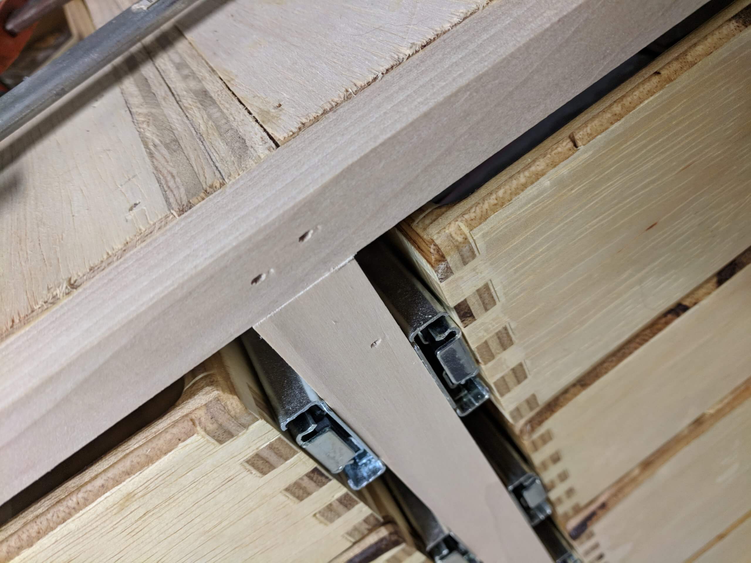
I used 21 3/4″ 100lb full extension drawer slides from Woodworker’s Hardware. They are a good value and the company has great customer service. At this stage you need to separate each slide into an inner mount and an outer slide so that the outer slide can be installed in the carcass.
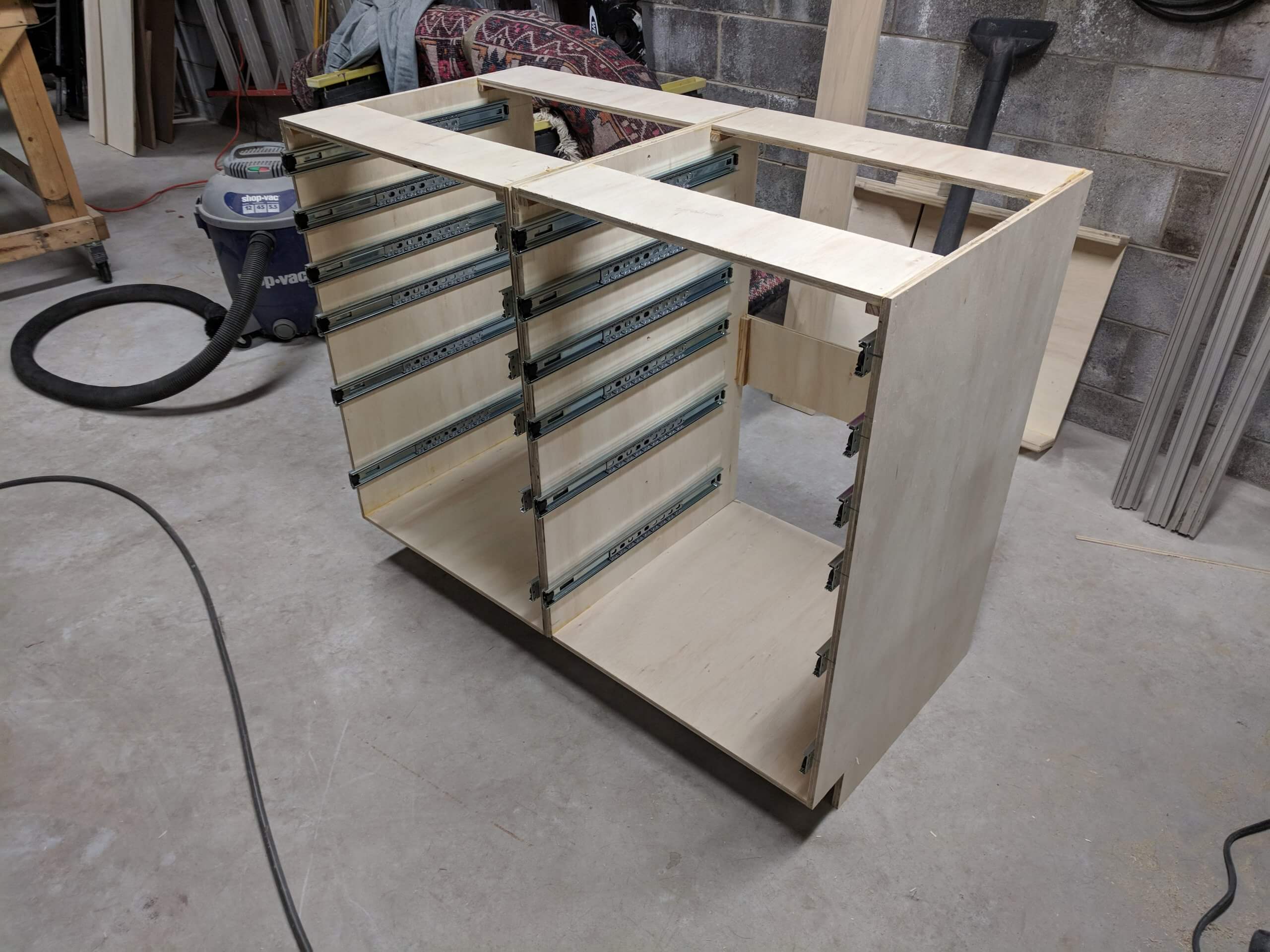
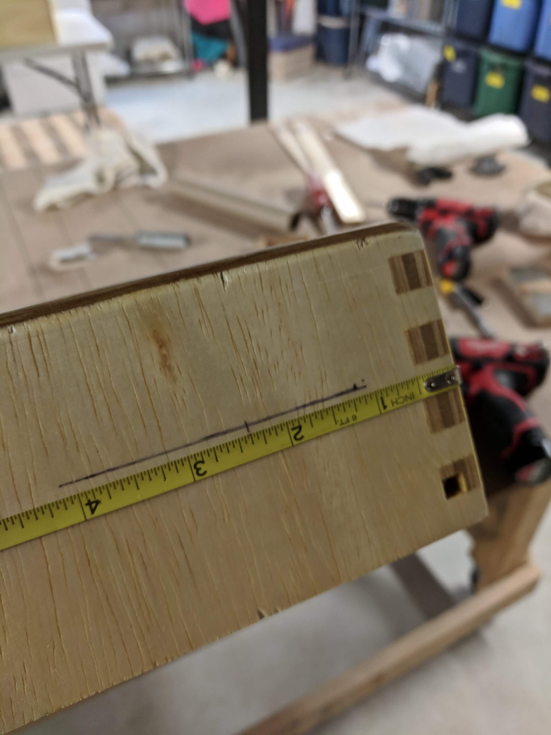
Slides are installed centered on the lines previously marked and the front of the slide is extended 3/4″ from face as the base units will be faced with 3/4 solid wood to hide the plywood grain. Install by marking the hole locations, center punching and then pre-drilling. If you are not facing your cabinets or drawers, then you can omit the 3/4″ extension.
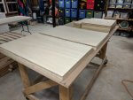
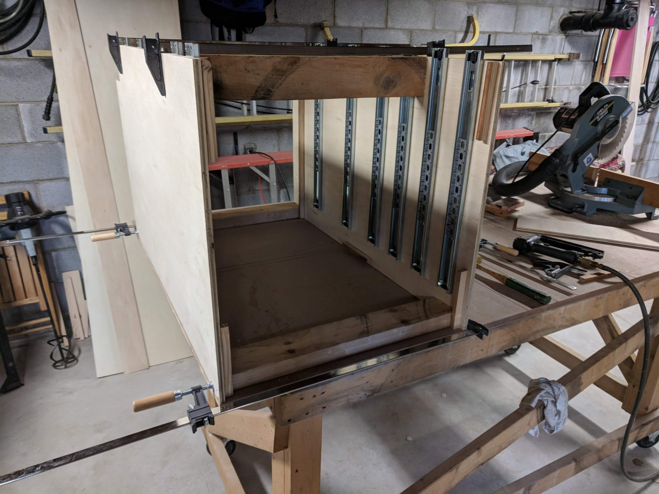
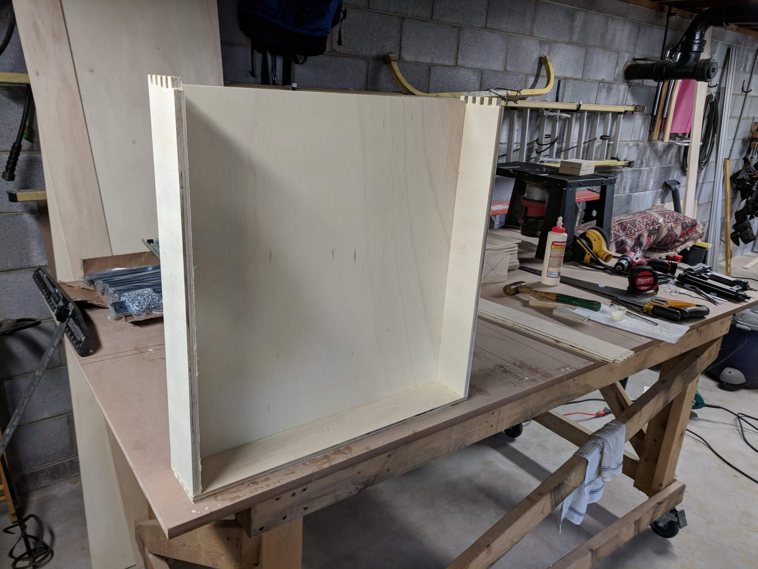
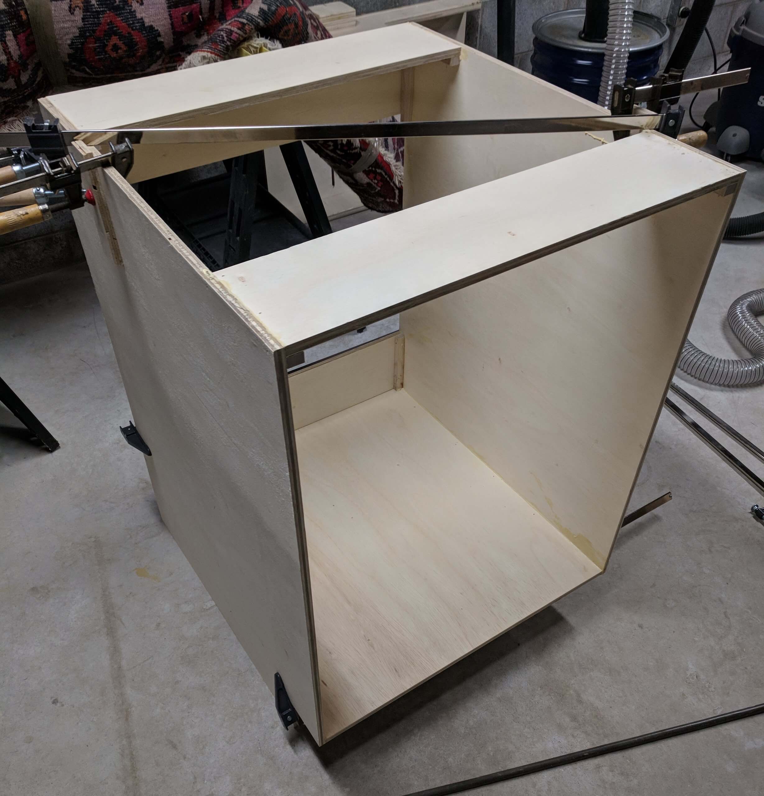
Once you have 8 sides assembled you are ready to clue up the base units. To aid this, I cut four scrap 2″X4″s to 23″ long to use as spacers to hold the cabinet square. I clamped these in place while the sides rested on a flat surface. Resting on a flat surface ensures that the cabinet is plumb. Square is ensured by aligning the front and sides to the square edge of the work surface. You should still check for square after putting in the bottom and the stringers.
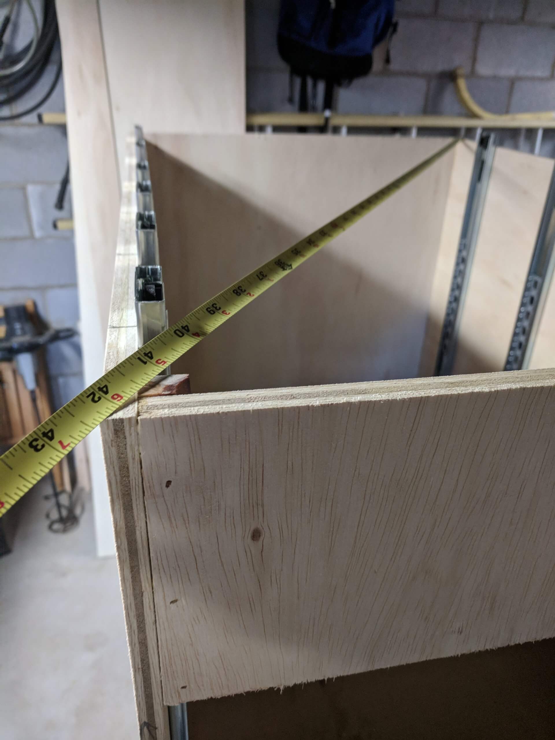
To check for square, measure from one corner to the other diagonally along the face. The two measurements should match. If they do not, the box forms a trapezoid with the longer measurement leaning out or forward. Tap the longer measuring corner and re-measure until the two are the same.
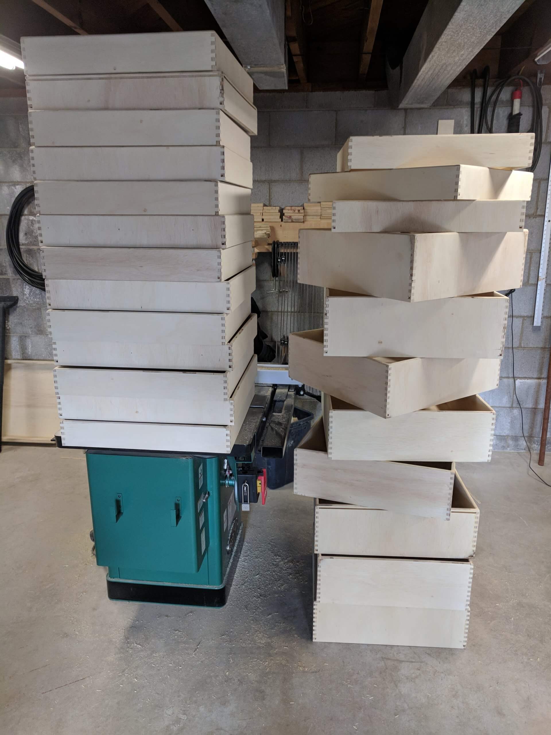
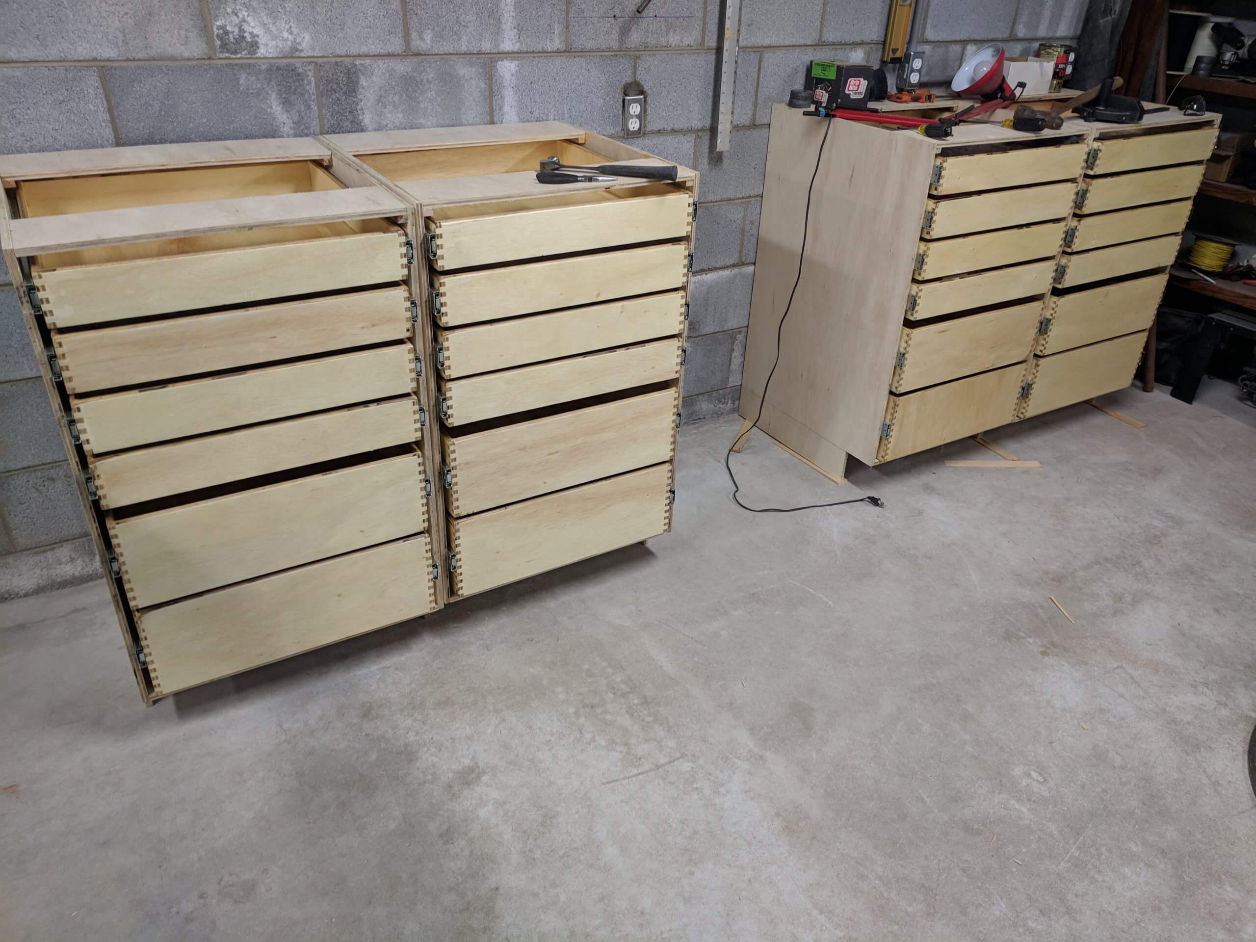
Allow each carcass unit to dry over night before removing it from the bench or flat surface as the glue is prone to racking if moved sooner. Also when you move the carcasses around at this point, be mindful that they lack a great deal of horizontal stability without the countertop or wall mounting and could easily be moved out of square.
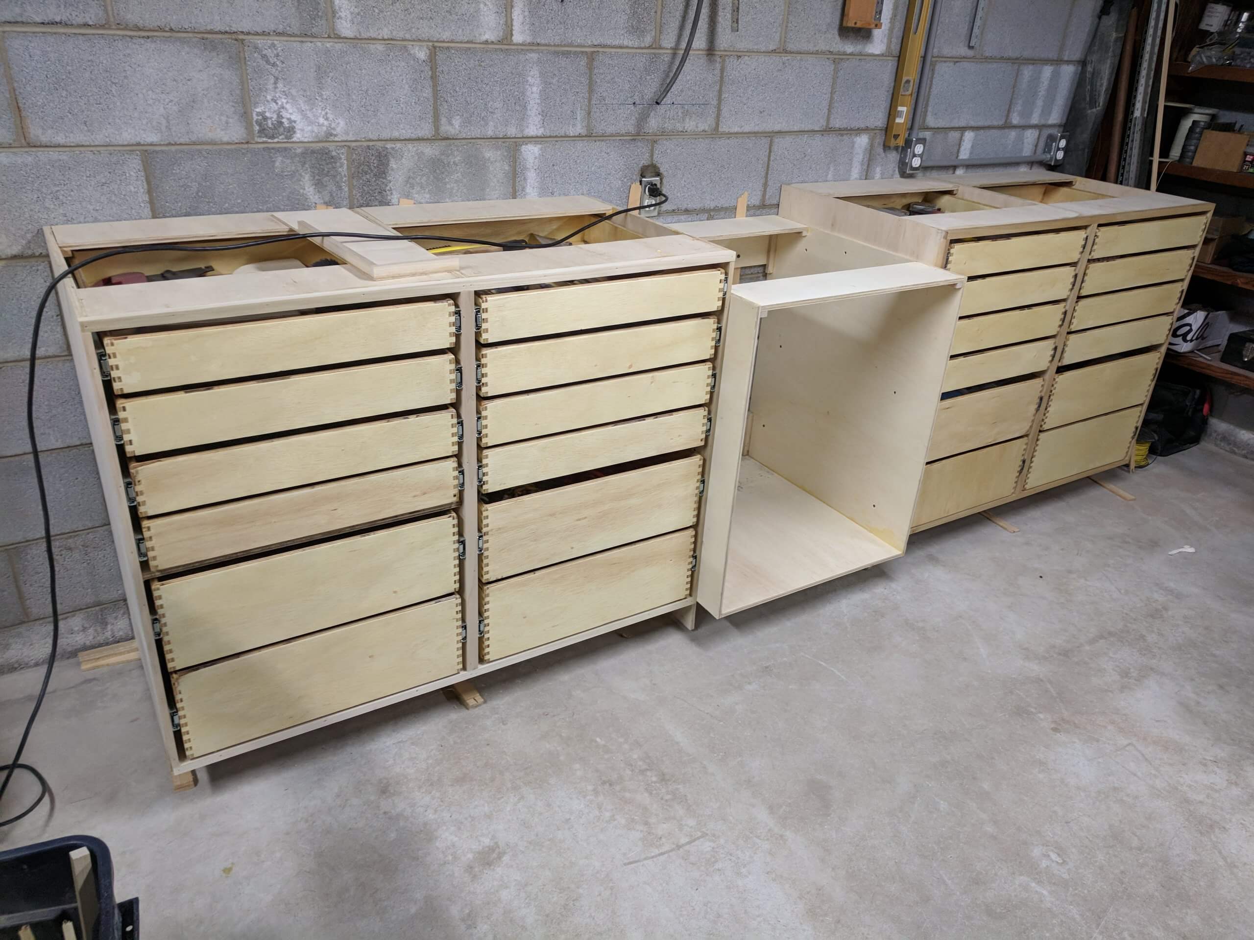
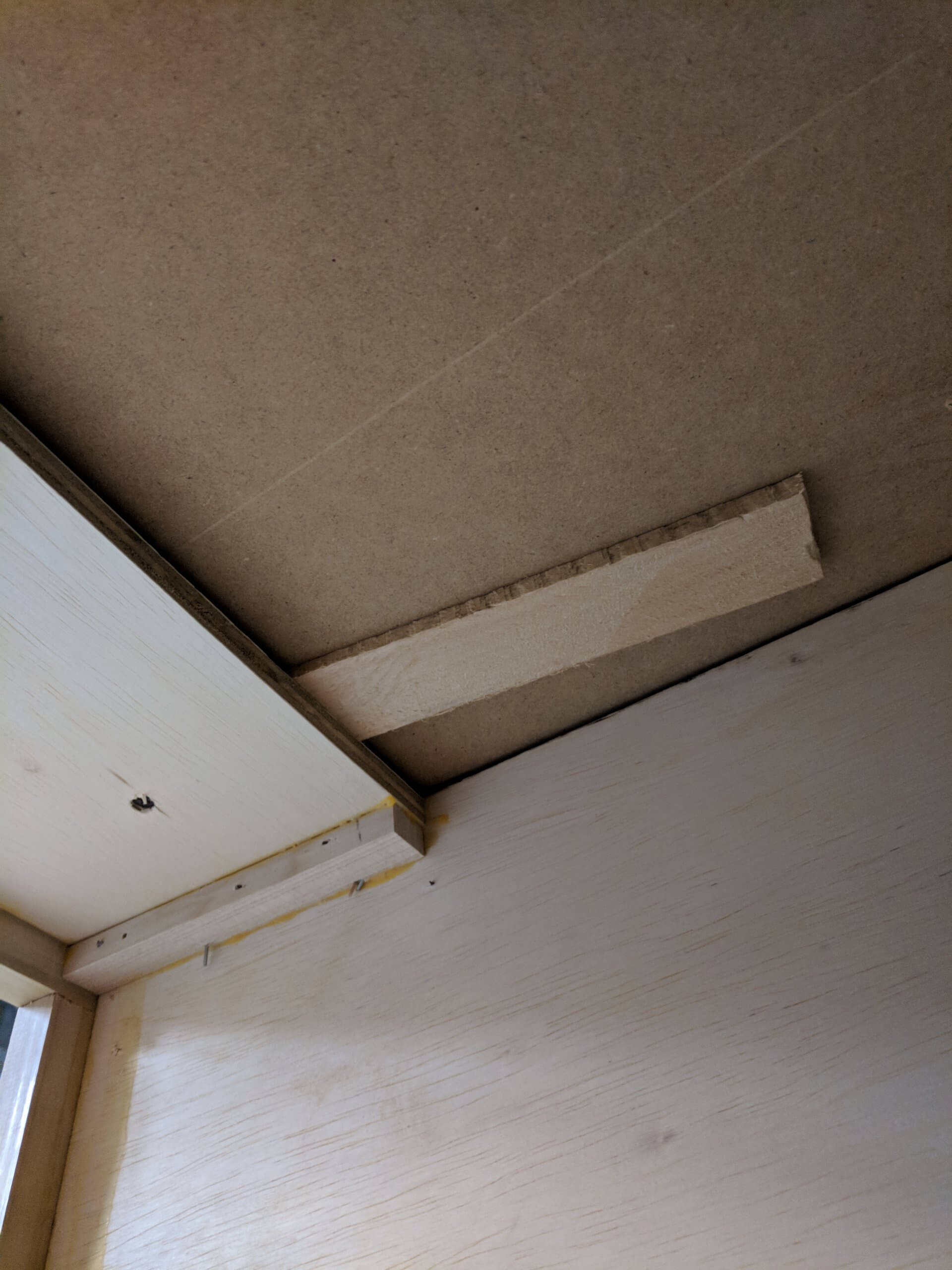
Store them out of the way while you make the drawers. Note that the top back stringer is omitted at this point.
Drawers
Drawers are simply accurately sized boxes. In this case the base unit opening is 23″ (same as the bottom and the stringers) and the drawer slides used require a 1/2″ clearance on each side so all drawers will be 22″ wide. Since the base units are 23 7/8″ deep, the drawers will easily fit being 22 7/8″ deep, leaving an inch at the rear for the stringer and mounting, so all drawers will be 22 7/8″ deep and 22″ wide. Each base unit as drawn has two 7 7/8″ tall drawers and four 3 3/4″ tall draws. If you are designing drawers yourself, your only limits are the width of the carcass, the clearance required for the slides and the spacing between drawers. Typical drawers have much more than a 1/2″ gap between them, but I like taller drawers so that I am not prone to put items into the drawer that will hinder its opening and closing.
Using 1/2″ plywood, this results in an inside drawer size of 21 7/8″X21″. It is customary to put bottoms in a 1/4″ deep dado slot and that would increase the size of the bottom 1/2″ in each direction resulting in a bottom that is 21 3/8″X20 1/2″. I prefer to leave the bottoms 1/8″ shy of the finished size to allow for error and/or expansion, so the final bottom size for all drawers is 21 1/2″X20 3/8″.
The bottoms of these drawers will be glued in as the sides are plywood. If the sides were solid wood they would not be glued in so that the sides could expand and contract.
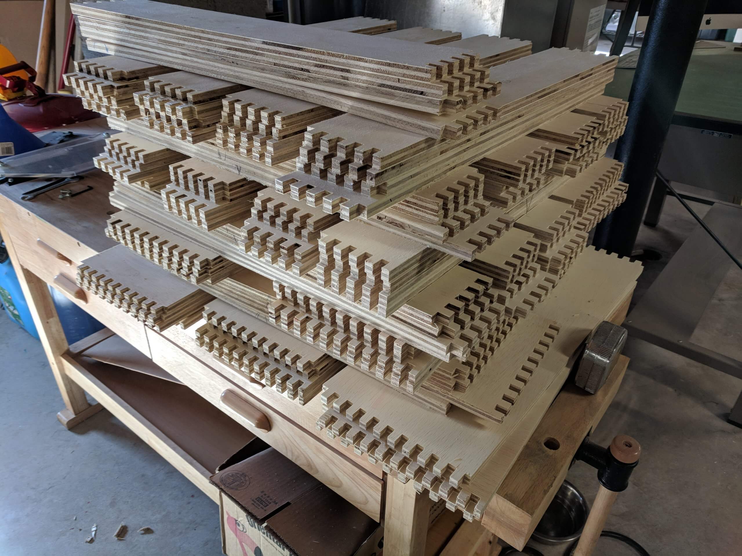
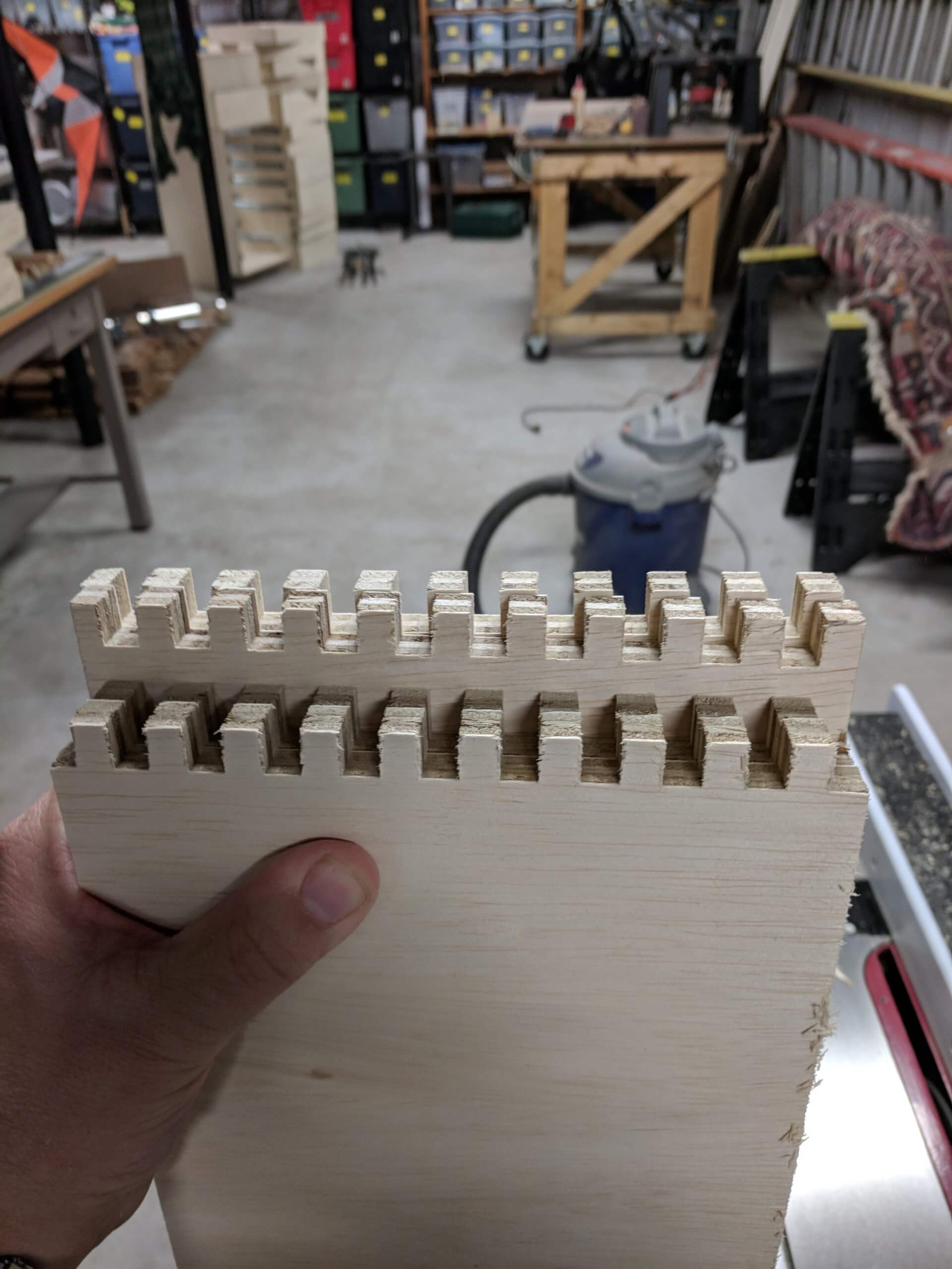
The drawers in this design are assembled with finger joints, so the sides, front and back are cut to the finished size of the box. If you use a different joinery method, adjust the length to compensate. Finger joints are strong but a bit time consuming compared to butt joints or lap joints.
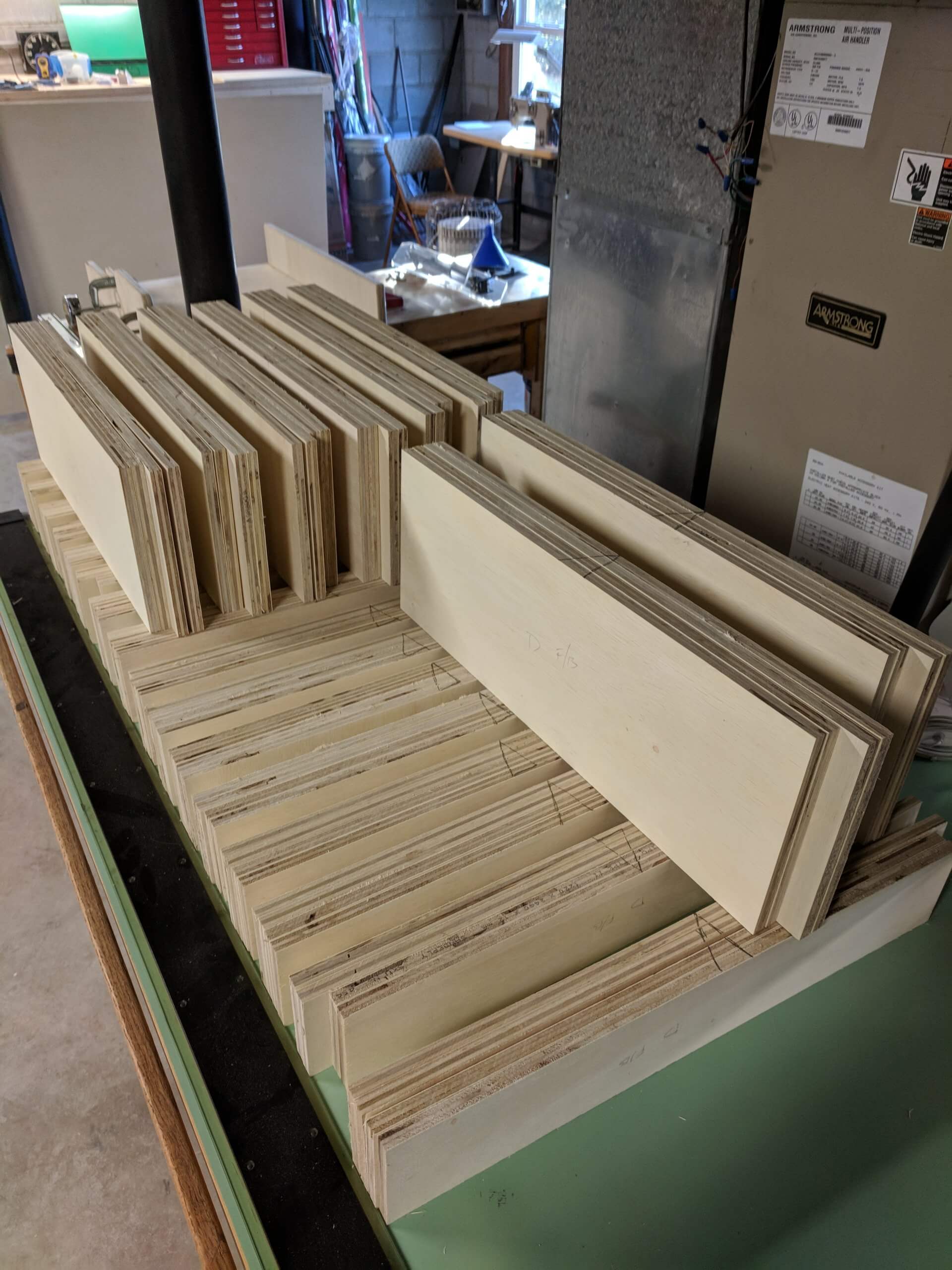
The parts bill for the drawers are 32 sides 3 3/4″ tall by 22 7/8″ long, 32 fronts/backs 3 3/4″ tall by 22″ long, 16 sides 7 7/8″ tall by 22 7/8″ long and 16 sides 7 7/8″ tall by 22″ long. As you can see from the cut list in the model, you can get the parts out of the sheets fairly efficiently.
Drawer joints can be anything you like, but I plan on putting a good bit of weight in my drawers (power tools, air tools, nails etc) and will be using finger joints. If you want to use a simple lap or dado joint, you can. Just reduce the length of the sides by 1/2″ and cut a 1/4 inch deep dado 1/2″ wide in the sites of the front and back.
Once cut, group drawer parts into sets and place all rough grain portions on the “bottom”. I also mark on the part what it is (side or front/back) and place that mark on the “bad” side. When the drawer is assembled, the “good” side will be towards the inside of the drawer. With the sides grouped, place a witness mark on the bottom as this will be used for all machining operations.
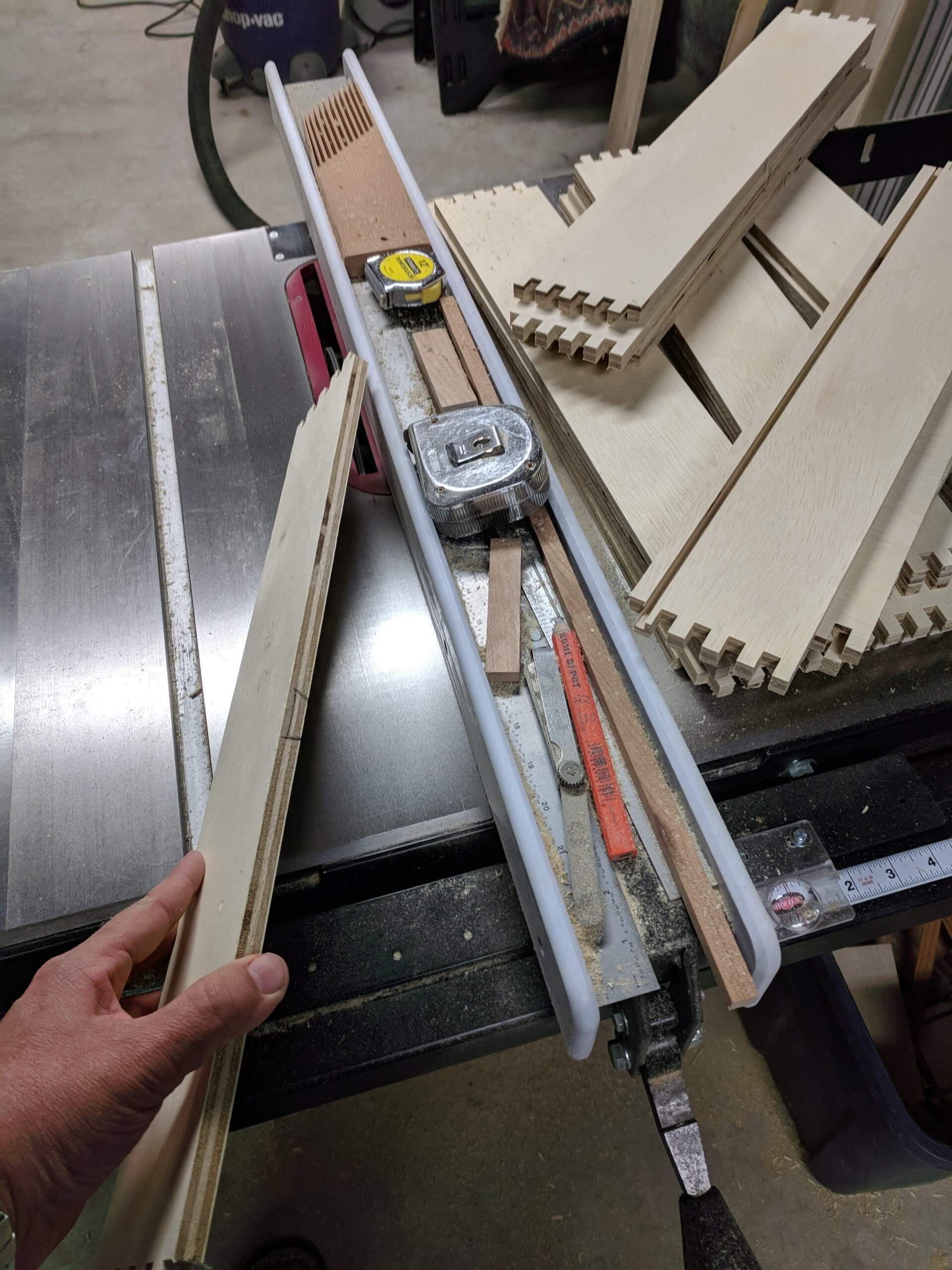
I used a finger joint jig that attaches to a miter slide used on a table saw. How to make the jig and finger joints in general are beyond this how-to, but there are ample sources of information on the Internet. My favorite is by William Ng. His method is simple and efficient. It is essential to use the witness mark with finger joints so you end up with boxes that align.
As Ng points out, you use the two sides or front/back if you cut them first to align the correct spacing of the next two parts. He recommends a finger that is .006″ smaller than the opening, but for the cheap plywood I used, .010 is better.
Once all of the milling is done for the finger joints, you can cut the slot for the draw bottom. Some use multiple passes on a standard blade, but since you are already using the dado for the finger joint process, it is just as easy to set the data to 1/4″ and cut your 1/4″ deep slot. You can cut the slot at any height you prefer, but I like it to align with the bottom second finger joint, so mine is 3/8″ in.
As you cut the slot for the bottom, be mindful of the witness mark so you get the slots cut on the bottom and on the inside face. With 96 sides to slot, I ended up make a few mistakes, largely from drawer sets that I changed my mind on the “bottom” of and had a scratched out witness mark. If you make a mistake, you will notice at at glue up as one side will have the slot on the wrong face. It is easy to cut another slot, so I left the dado in the saw while glueing up the drawers so I could at a slot if needed.
Prior to glueing up a set, position them and verify that the slot is correct, the finger joints line up as they should and there are no oddities as one it is wet with glue it is hard to correct.
To glue up the drawers, I use a flat work space and layout all the parts of a drawer then liberally apply glue to the finger joints and the drawer slot.
Assemble the the front with two sides then slide in the bottom from the missing back and place the back on. Depending on the spacing of your joints, this may take some persuasion with a mallet. Use blocks and a mallet to get the joints closed prior to clamping as using a clamp to close them up will simply create warped drawers. With finger joints and clamps, there is no need for any fasteners.
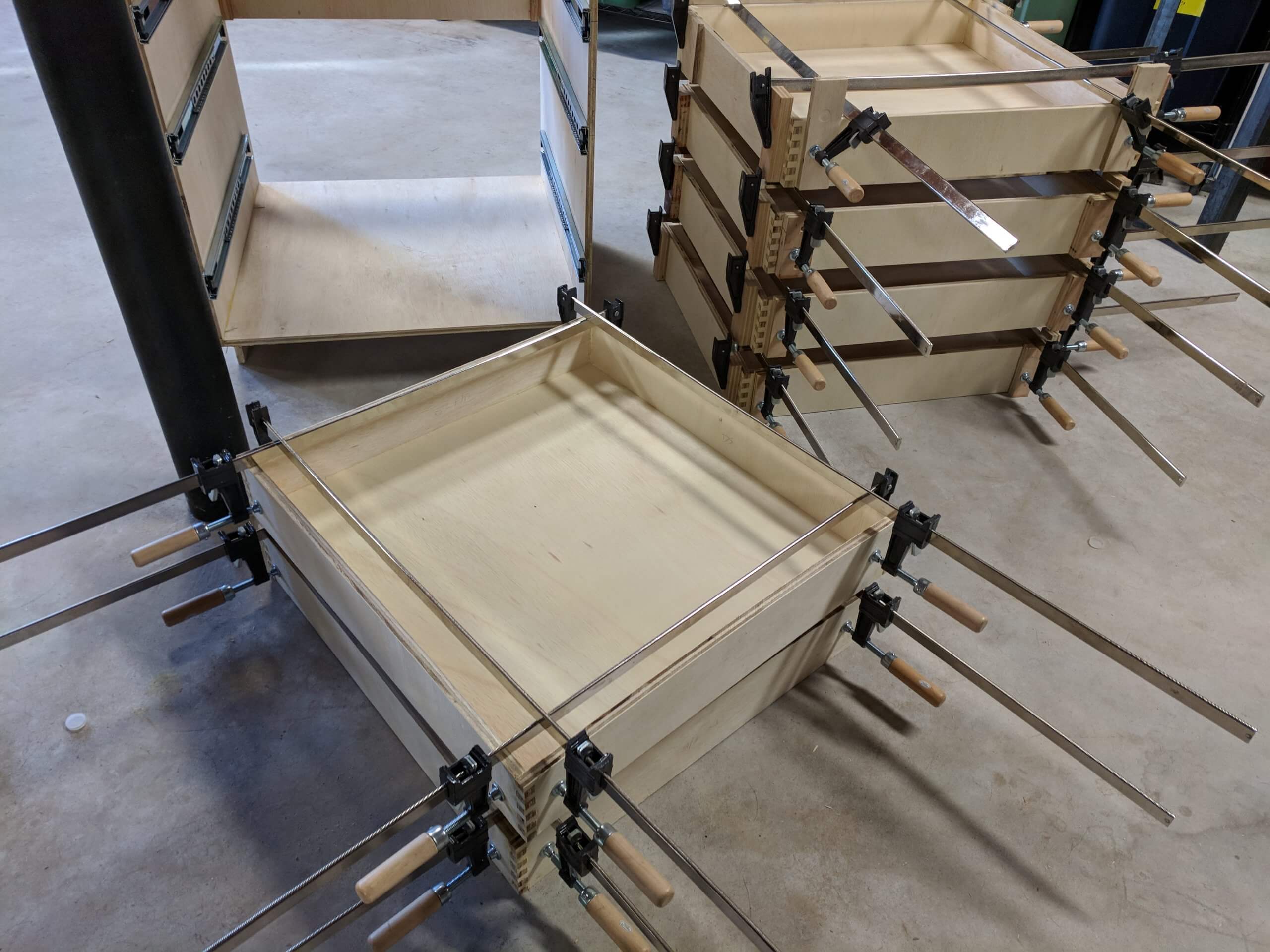
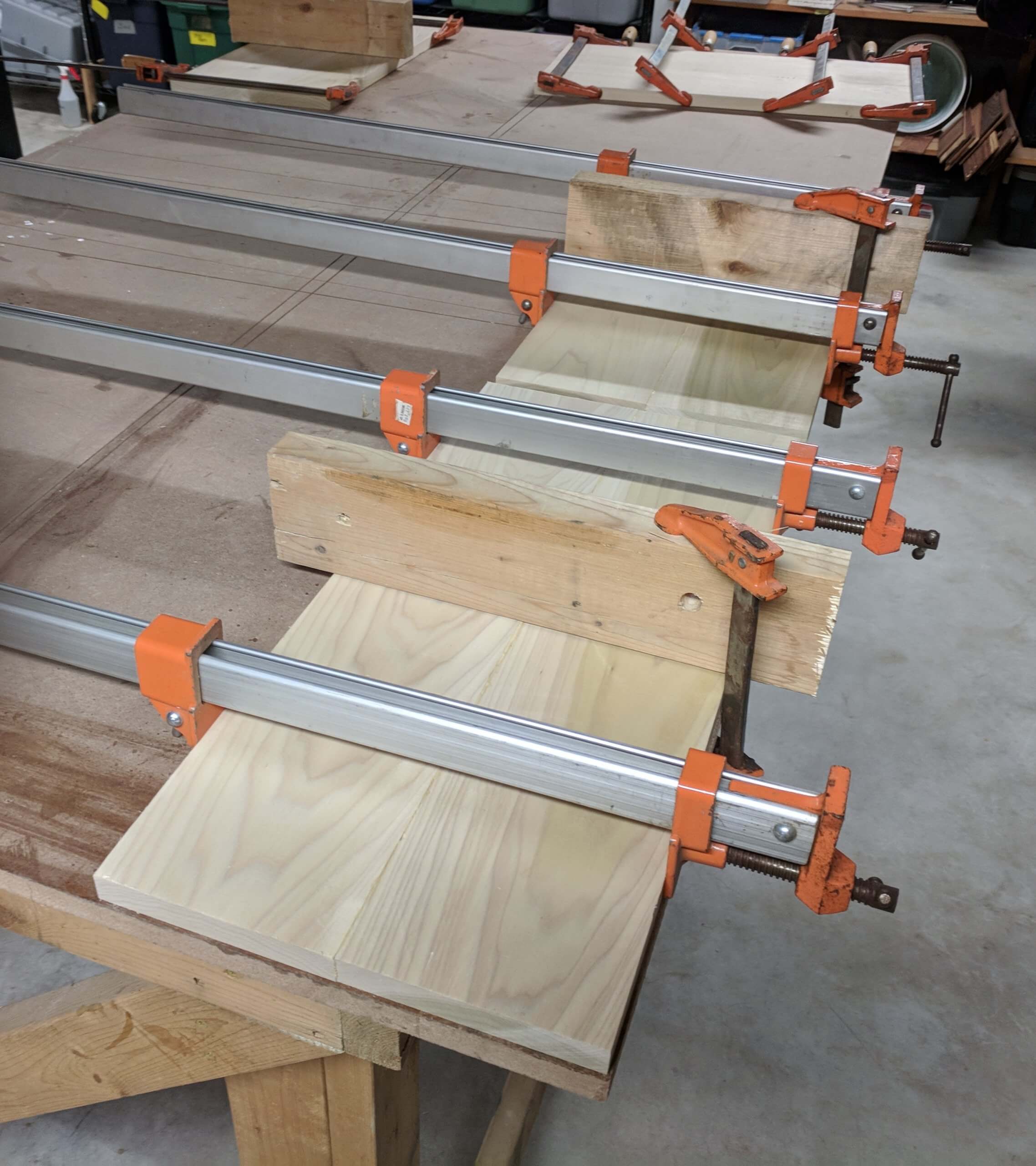
After the drawer is assembled, clamp it liberally and place on a flat surface to dry. I had 24 clamps large enough for these oversized drawers, so I was limited to six drawers drying at a time.
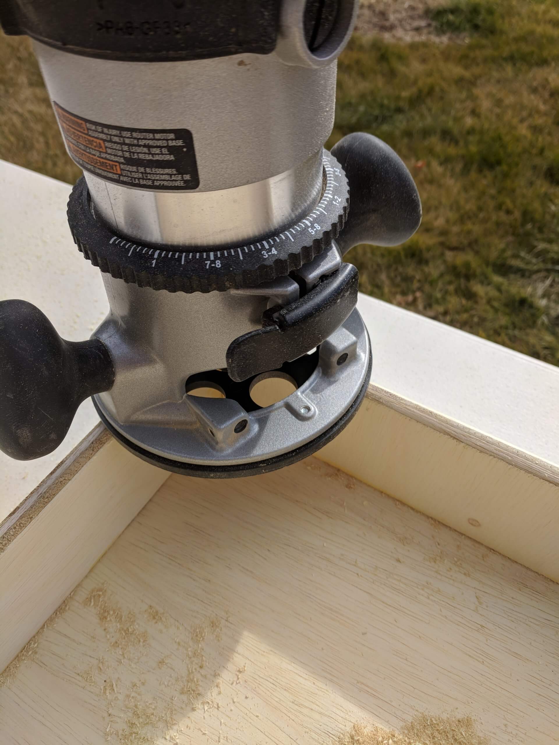
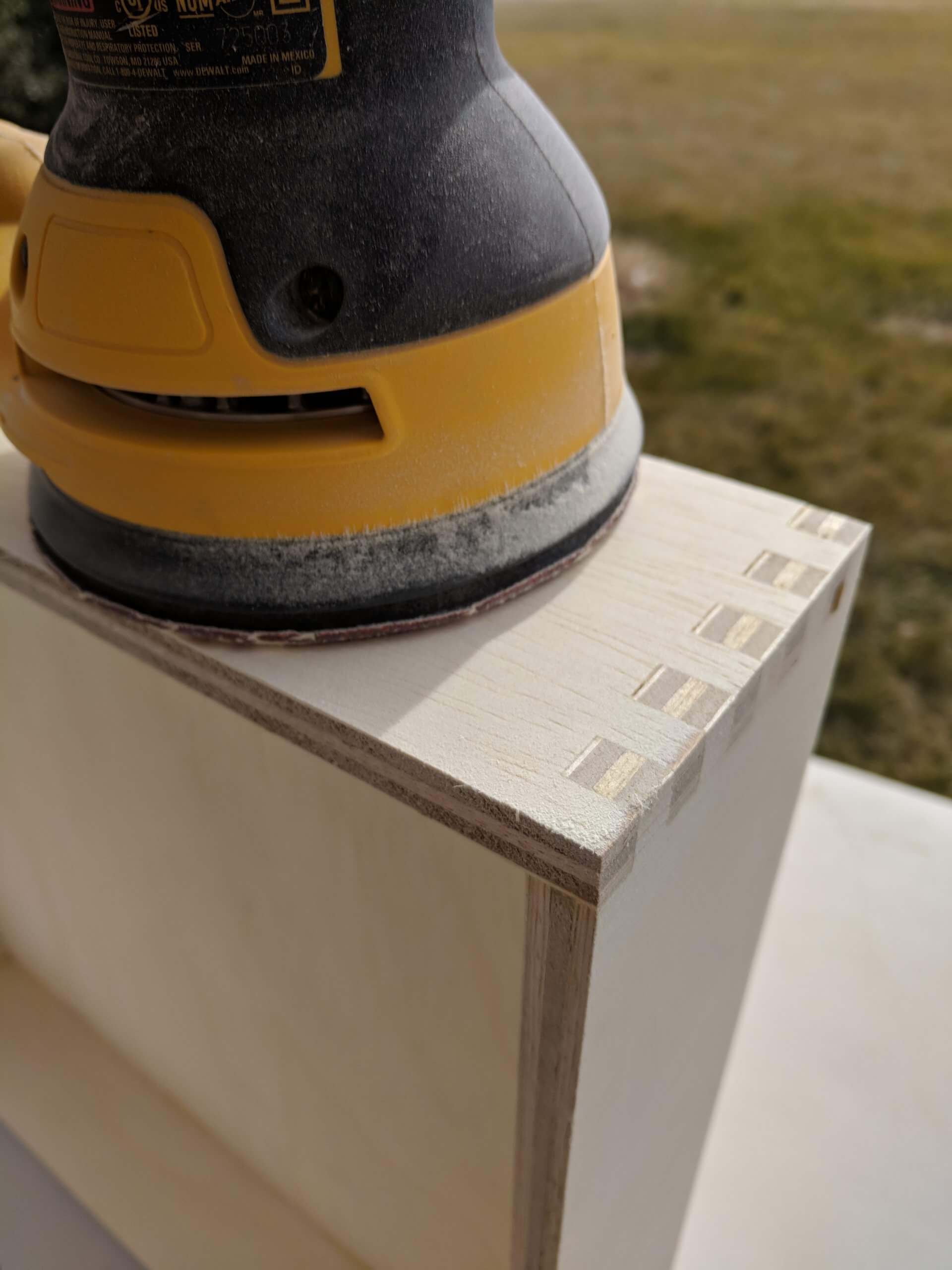
Finishing options are a mater of personal preference, but I wanted to ease the edge of the drawers, so I rounded them over with a 1/4″ router bit, then sanded all surfaces #80 grit using an orbital sander.
As I will be putting tools in many of these drawers, I put two coats of polyurethane on the drawers so they would not absorb dirt and other items from the tools. I sanded the drawers with #220 grit between coats. I won’t lie. This took a LONG LONG time. 24 drawers are a lot to sand finish, sand and finish again. You could get buy with one coat if you used lacquer, but I used polyurethane and it raised the grain and needed sanding and a second coat.
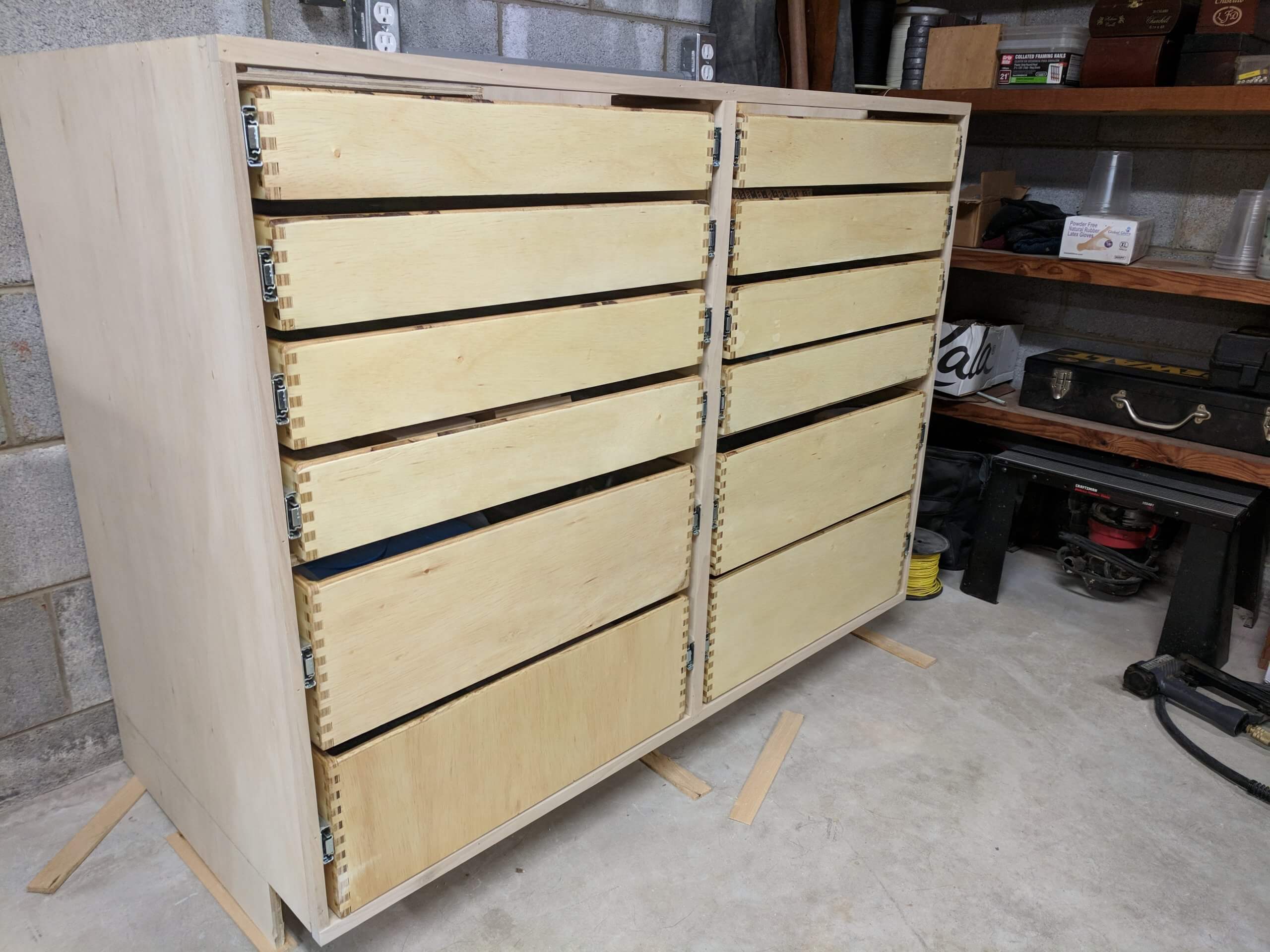
The final step in make the drawers mission ready is to install the slide mount. Draw a reference line down the center of the drawer and install the mount flush with the face of the drawer. Since we have already installed the slides in the cabinets based on the center of the drawer, you can safely install the slide mount on the drawer in the dead center. You can test fit the drawers and some will be fine with others being snug. At this stage the carcasses have some lateral movement an the width of the opening will not be set until it is installed. Save any tweaking of the carcass until they are mounted in their final location and if needed you can make adjustments then.
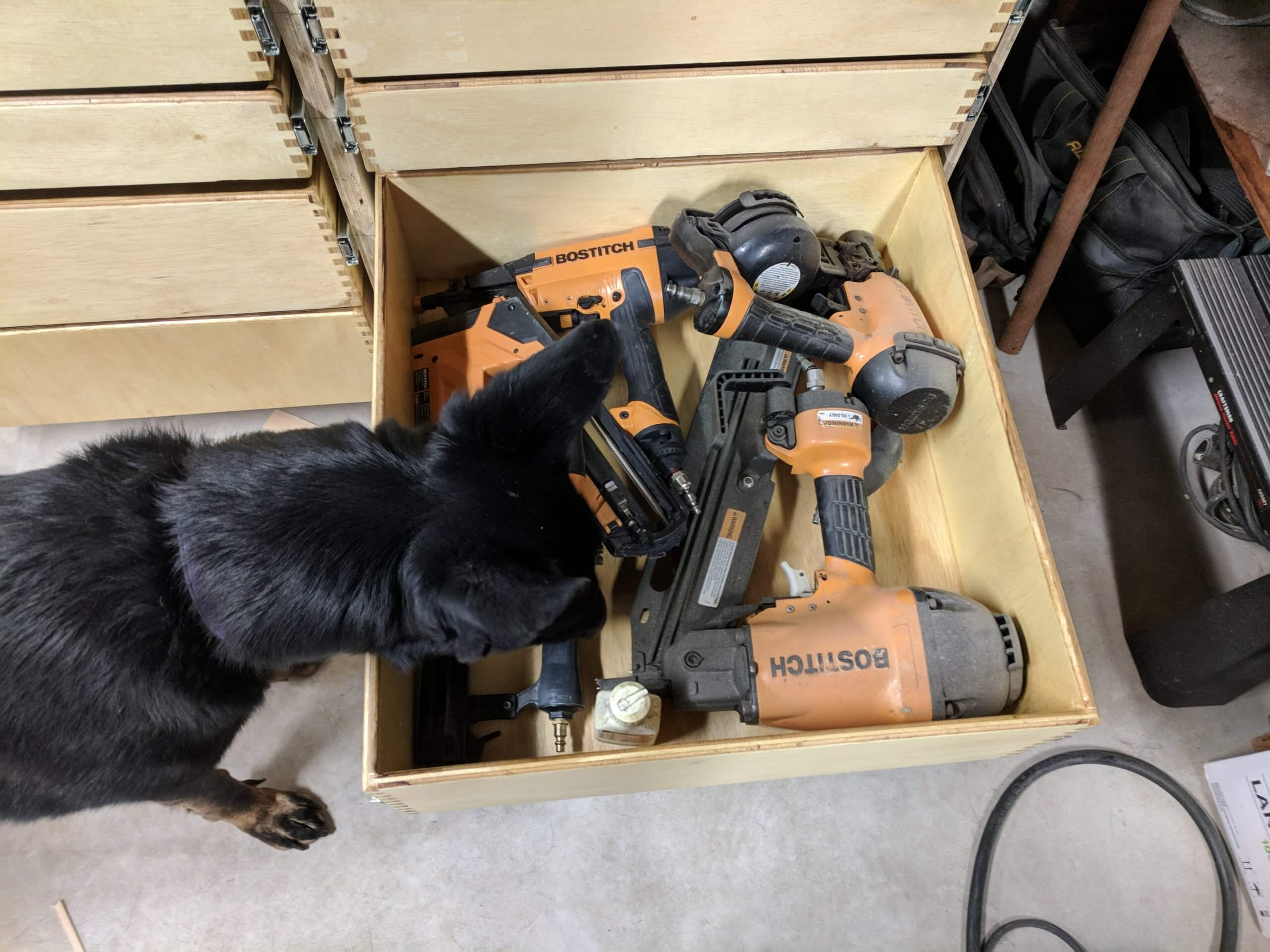
The 100lb full extension slides hold a great deal of weight! In order to mount the cabinet, I had to remove my old one so i needed to put the tools before finishing.
Center Cabinet
The center cabinet is generally identical to the side cabinets except there are no drawer slides and its height is reduced by the height of the miter saw you will use, its width is determined by the width of the saw at its widest and its depth is determined by the depth of the saw from wall to front mounting.
Keep in mind the cabinet described fits my saw, and the measurements are given only as a guide. You should be making the center cabinet for your saw.
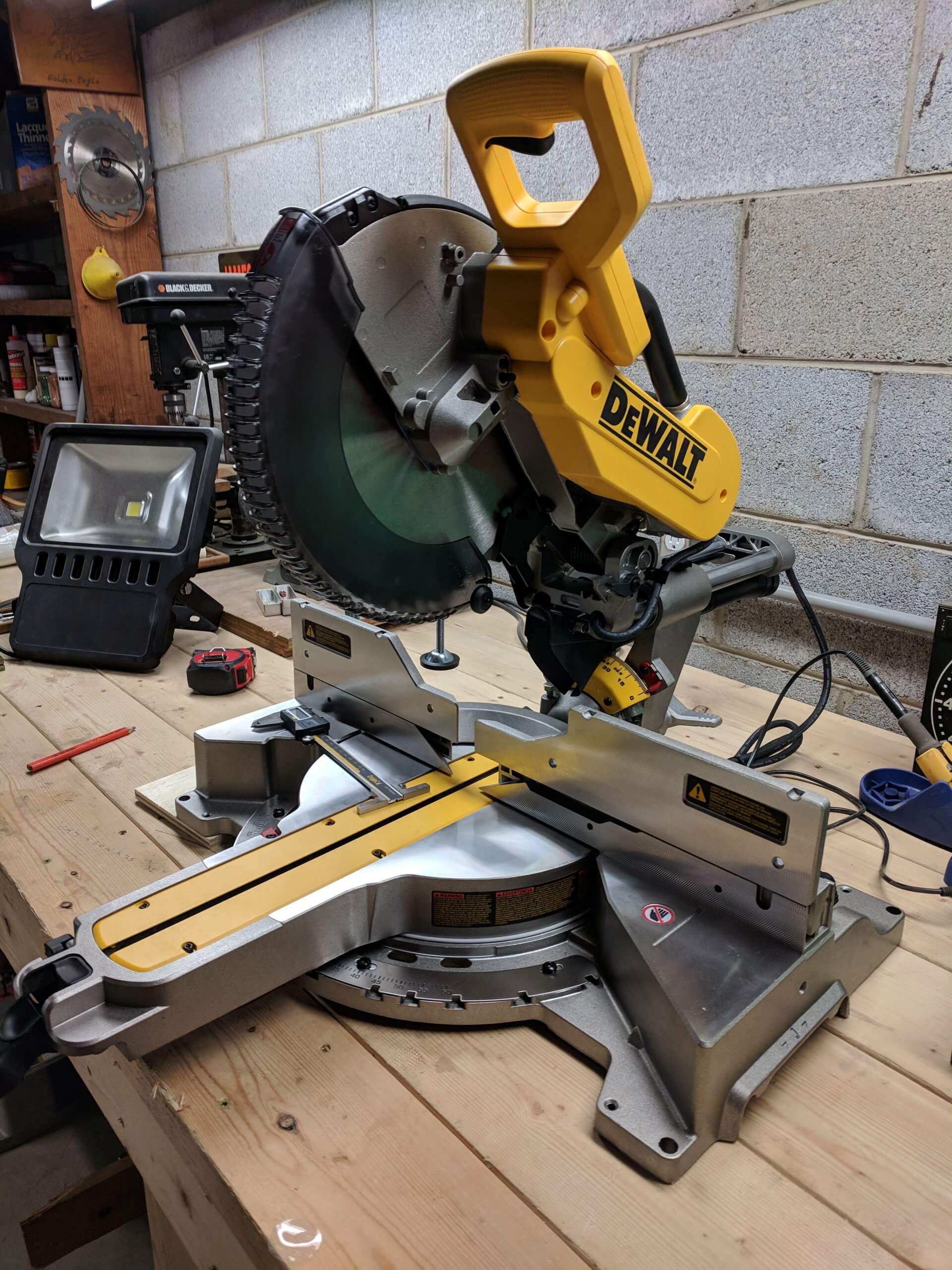
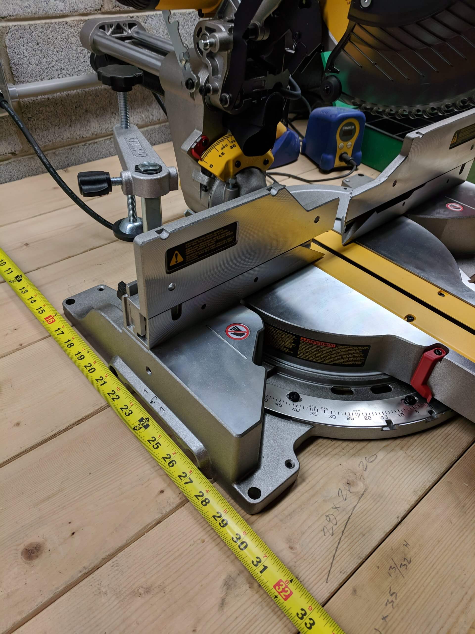
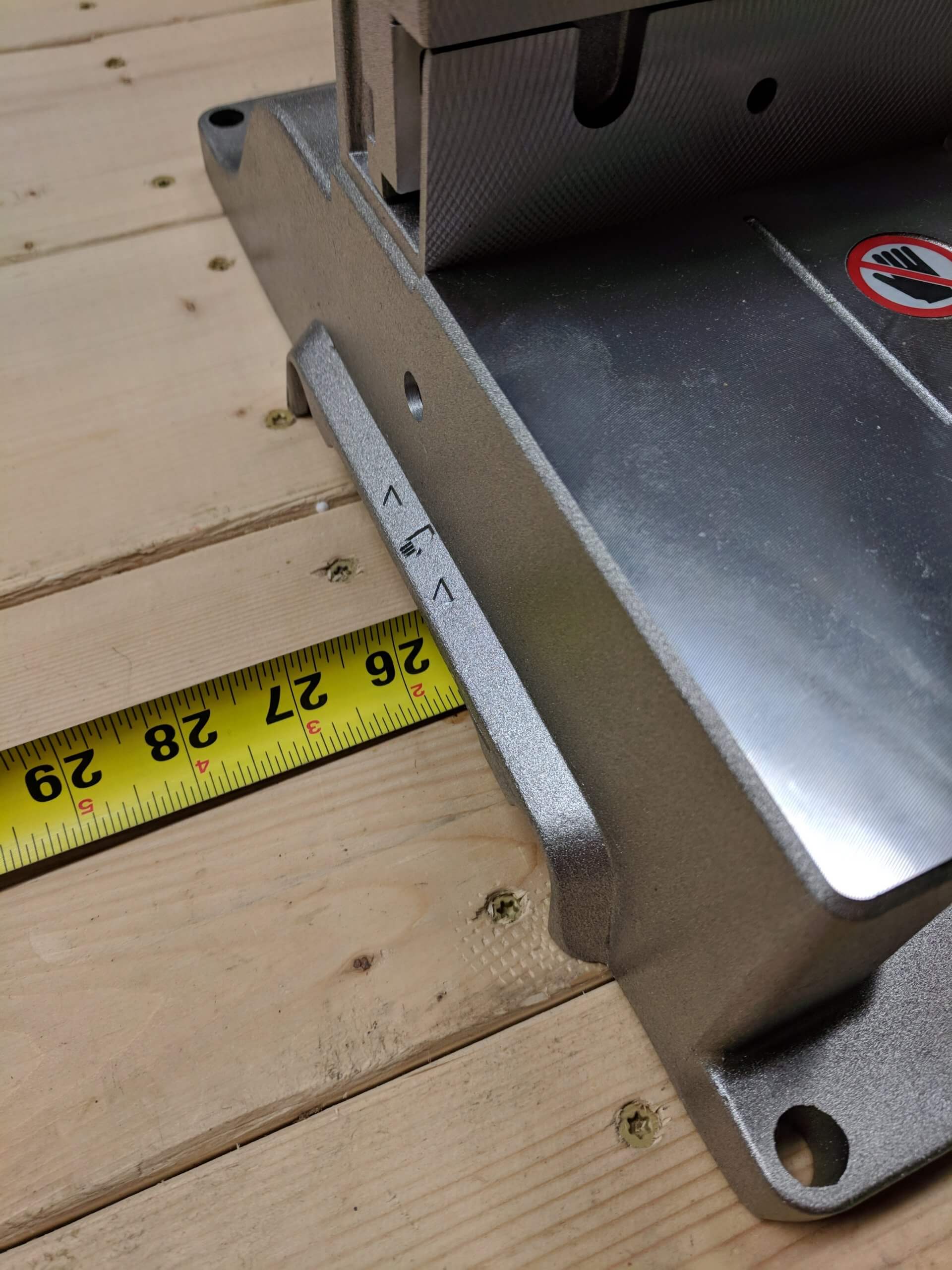
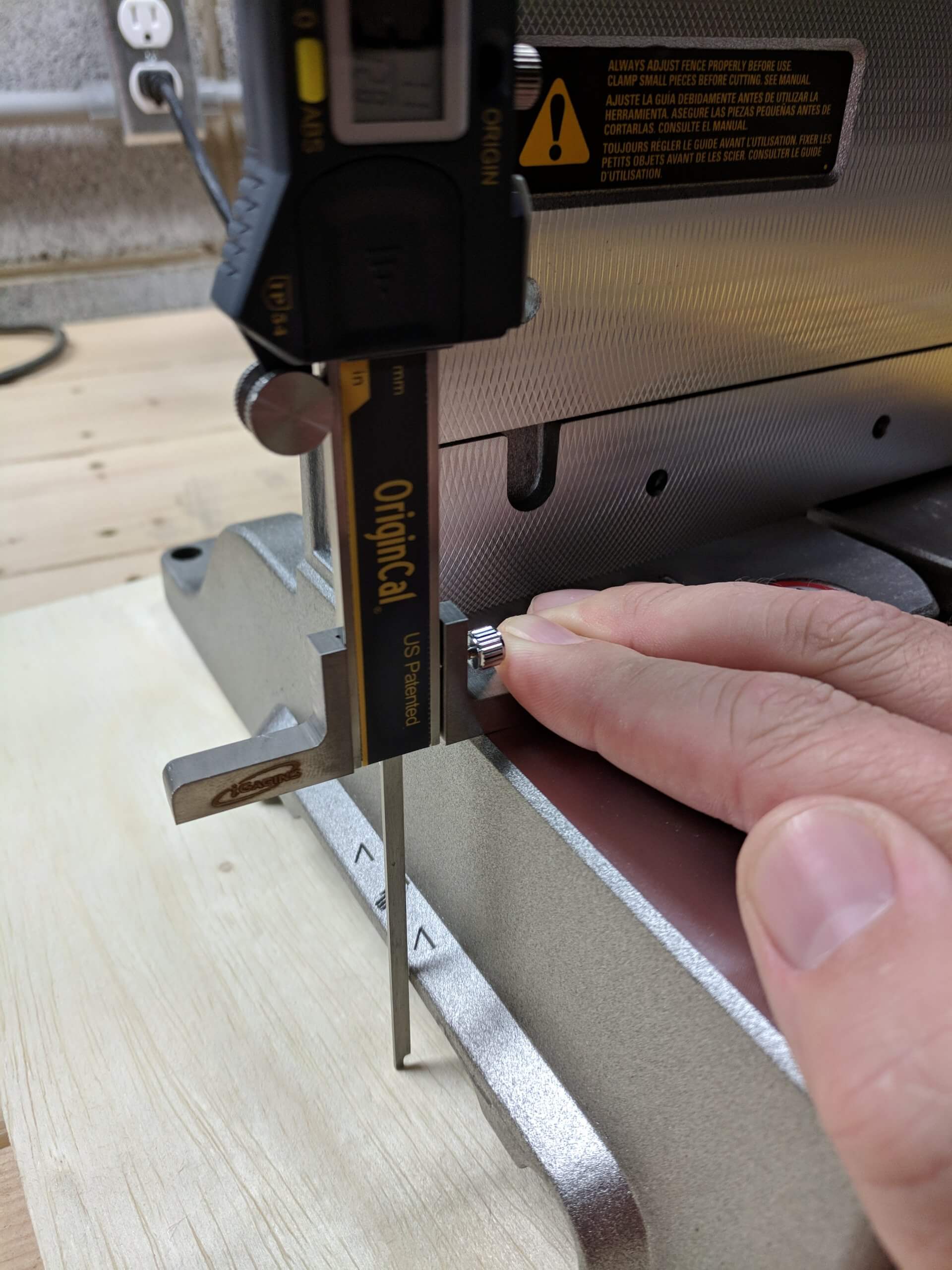
The first step is to measure your saw depth from the wall with the slide push all the way back. For my 12″ Dewalt DWS779, the depth is 29 1/2″. Then measure the width. Mine is 26″. Finally measure the height preferably putting the saw on a flat surface. Mine sits 3 17/32″ above the bottom of the base.
From these measurements we know we want a based cabinet that is 26″ wide. Since we will use a 2″ overhang for the countertop, we can use a 28″ deep cabinet. Finally, given that the left and right cabinets are 39″ tall, we want a height from the ground that is 39″ – 3 17/32″ – 1/8″, or 35 11/32″. Why the 1/8 shorter? Since it is not likely to end up with an exact fit for the saw base height, you want to error on the side of the saw being slightly low when sitting on the center cabinet so you can shim it to perfect height. If you error on making the center cabinet too tall you are basically out of options. I will shot for 1/8″ low and shim it level with the outer cabinets. Finally, the thickness of the countertop is moot at this point as the side cabinets and the middle cabinet will have the same top they are not a factor in your deductions for the height of the saw.
The parts list then for my cabinet are two sides that are 35 11/32″ X 28″. A bottom that is 25″ X 28″ and four 6″ stringer that are 25″ long. The bottom and stringers are 1″ shorter than the cabinet width. If you want a shelf, you just make another 25″ X 28″ bottom. I am leaving out a shelf as I plan to put virtical pull out shelving for saw blades and other tall items in the future. You will also need two doors that are 12 3/4″ wide by 34 27/32″.
Once cut out, cut the toe kick as before and assemble as before with the same wood facing if used.
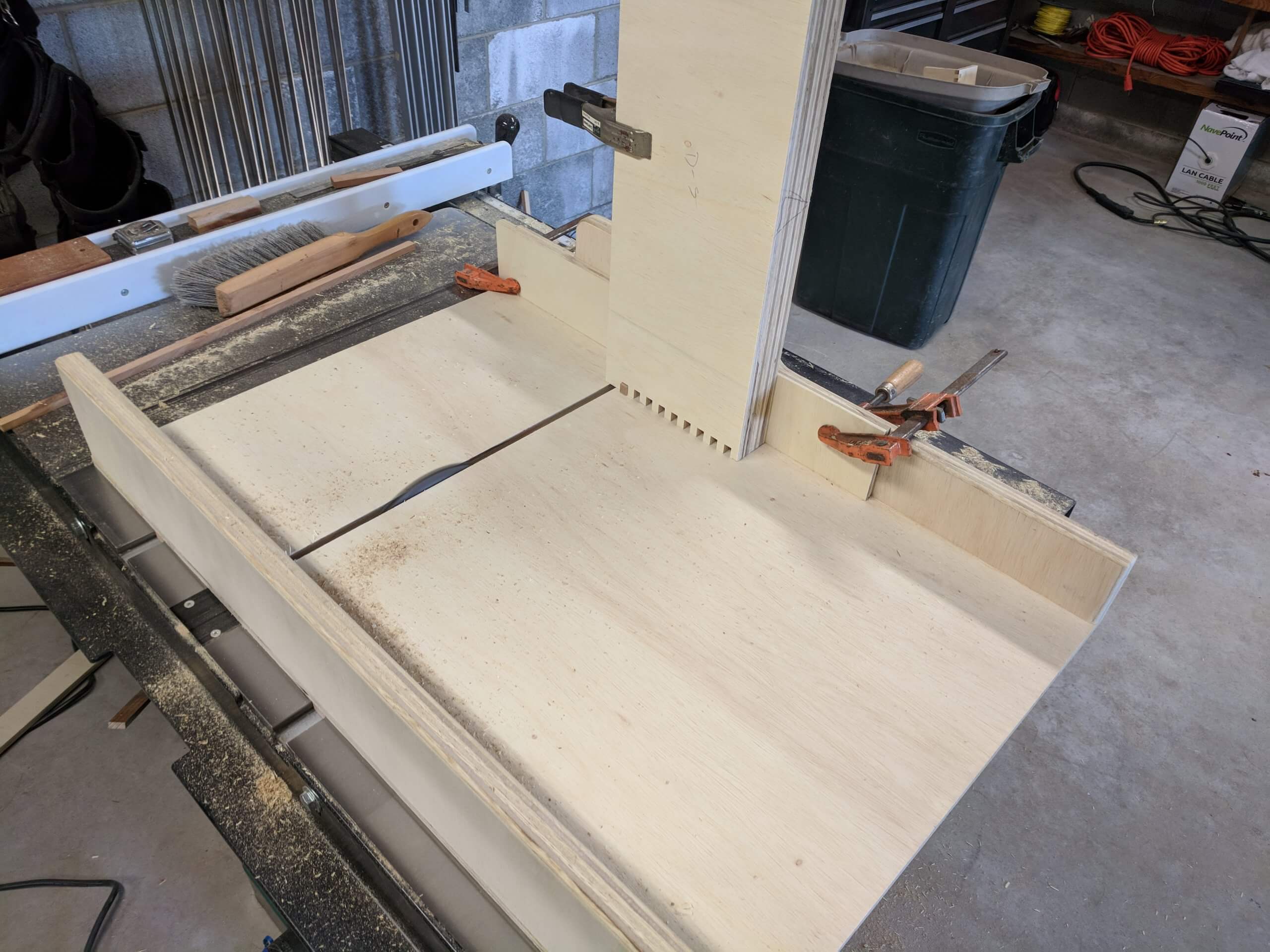
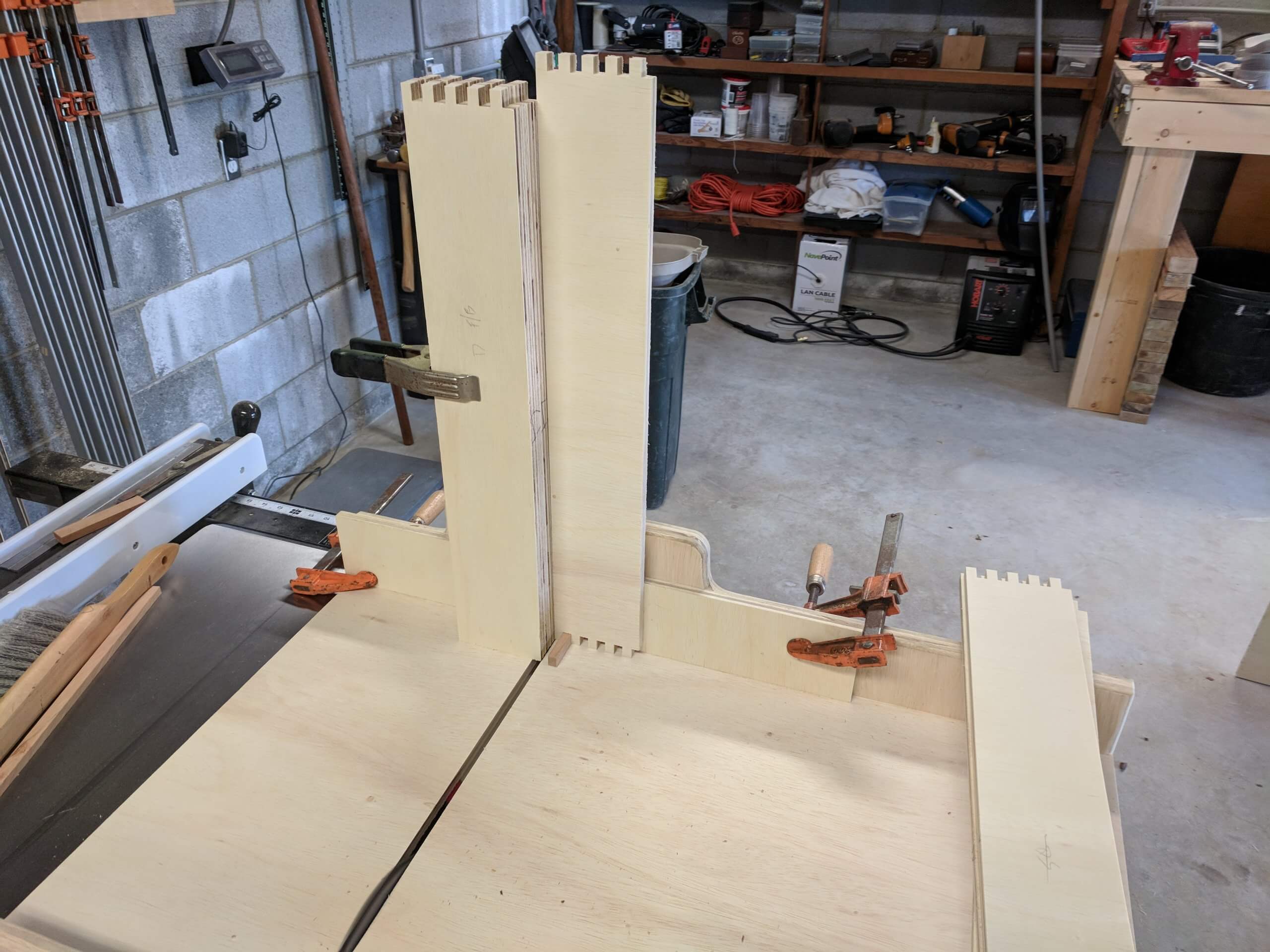
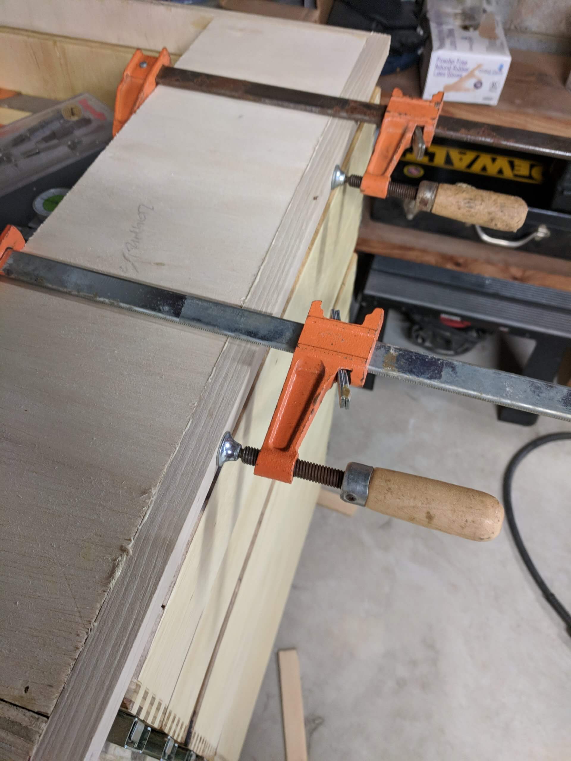
In the image of the glue-up for the center cabinet, note the diagonal clamp. The cabinet had a slight out of square rack and the clamp was used to pull it into square while it dried.
Because the center cabinet will get a set of doors vs drawers, I faced it with 1 1/2″ poplar to give the doors enough of a landing area and still conceal the opening.
Why did I get the Dewalt? Well not that it matters for this write up and it is certainly too long already, but 1) it lacks a laser and a laser can’t be used for fine furniture anyway so you don’t want to pay for one 2) it has a long cross cut capacity 3) it is accurate and easy to adjust if you find it needed and 4) without the laser it is a great value.
Instalation
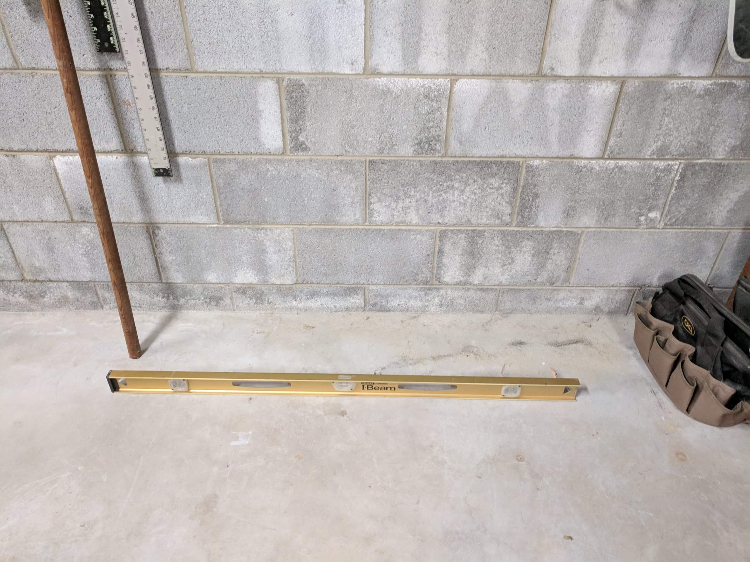
This section assumes you have constructed your center cabinet (described later). Carcass installation involves establishing a level plane for the cabinets to sit in. The first step is to assess the levelness of the floor and wall. You must assume that your floor is not level and that your wall is not square to the floor. I have installed a number of cabinets over the years and have never encountered a level and plumb wall/floor.
Assuming your cabinets are square, you will end up with a gap of some type along the floor and back. The objective of looking at your floor and wall is to determine the highest point of the floor and the most protruding point of the wall so you can start your installation there. If you start your installation at a lower point on the floor or further back point on the wall, it will be physically impossible to align the other cabinets as you will encounter a floor that rises, and the cabinet with it or a wall that starts to creep into the room and the cabinet with it.
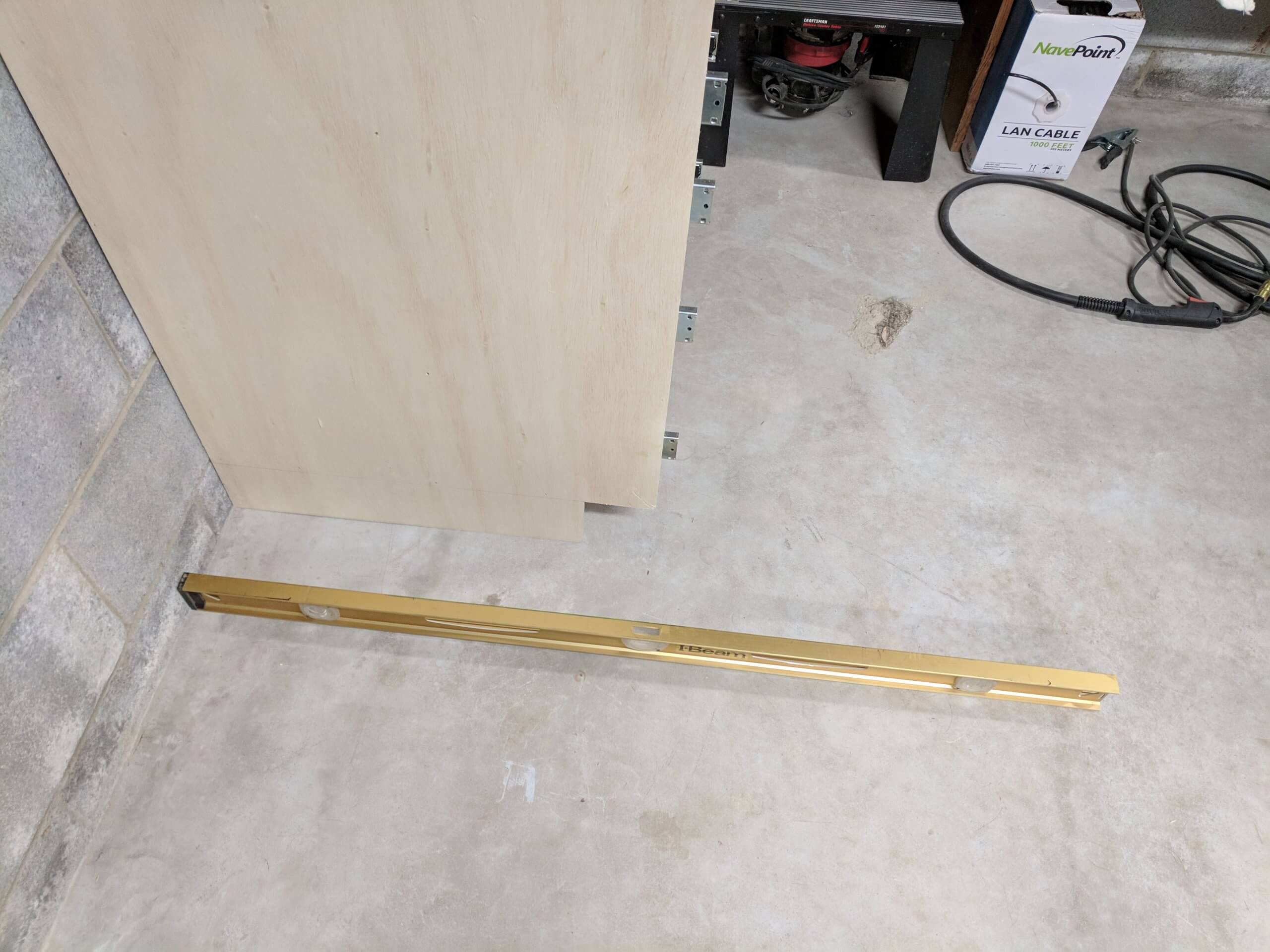
Once you establish the slope direction of your wall and floor, you can plan your installation, starting at the “top” of each slope. In my case the floor has a slight downward slope from right to left, so the right cabinet will be installed on the highest point, then each subsequent cabinet will be shimmed to raise it up to the level established by the highest cabinet.
Floor also slopes down slightly from the wall, meaning that the front of the cabinet will be shimmed up to establish level. My wall also leans away from the floor, meaning that if the cabinet were firmly mounted to the wall, it would raise the front even further from floor that is dropping off, so I will have to be careful to shim the rear wall mounting to that it tightens up with the cabinet still square.
Do you have to do this? It is not “essential” for regular cabinets. You can take what your house gives you, but if you take the time (and it will be time consuming) to install your cabinets square and plumb, your top will be flat and your drawers will work smooth. If you install your cabinets out of plumb, the drawers will tend to rack and you will have resistance opening and closing them. Given that this is designed to be a miter station, a top surface that is flat and parallel will be a good first step towards accuracy.
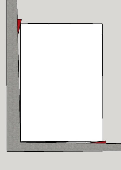
Here is a sketch to illustrate the shimming required. In this case the floor and wall slope away from each other and a square cabinet will need to be set level and plumb with shims at the low side of its mounting.
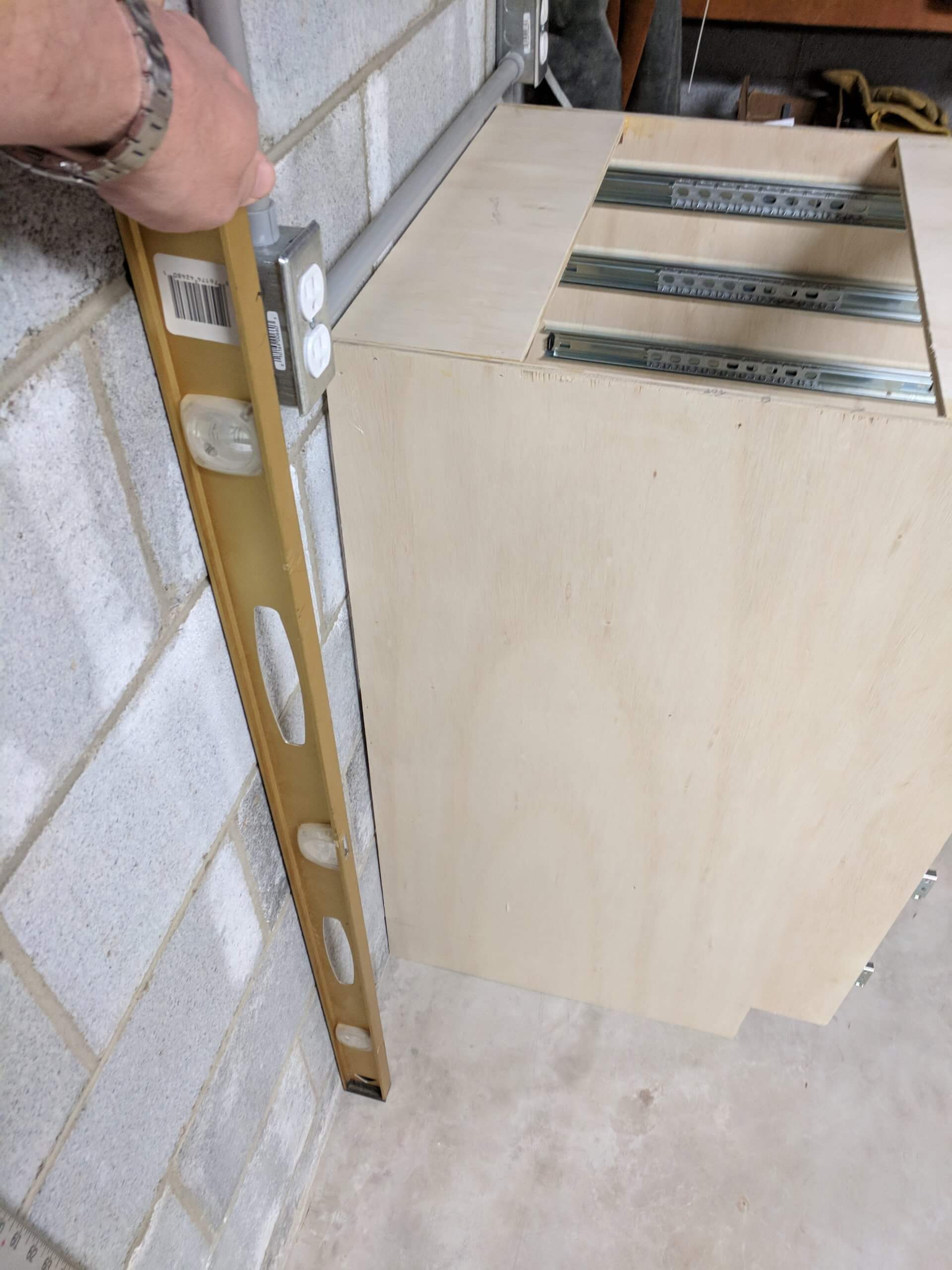
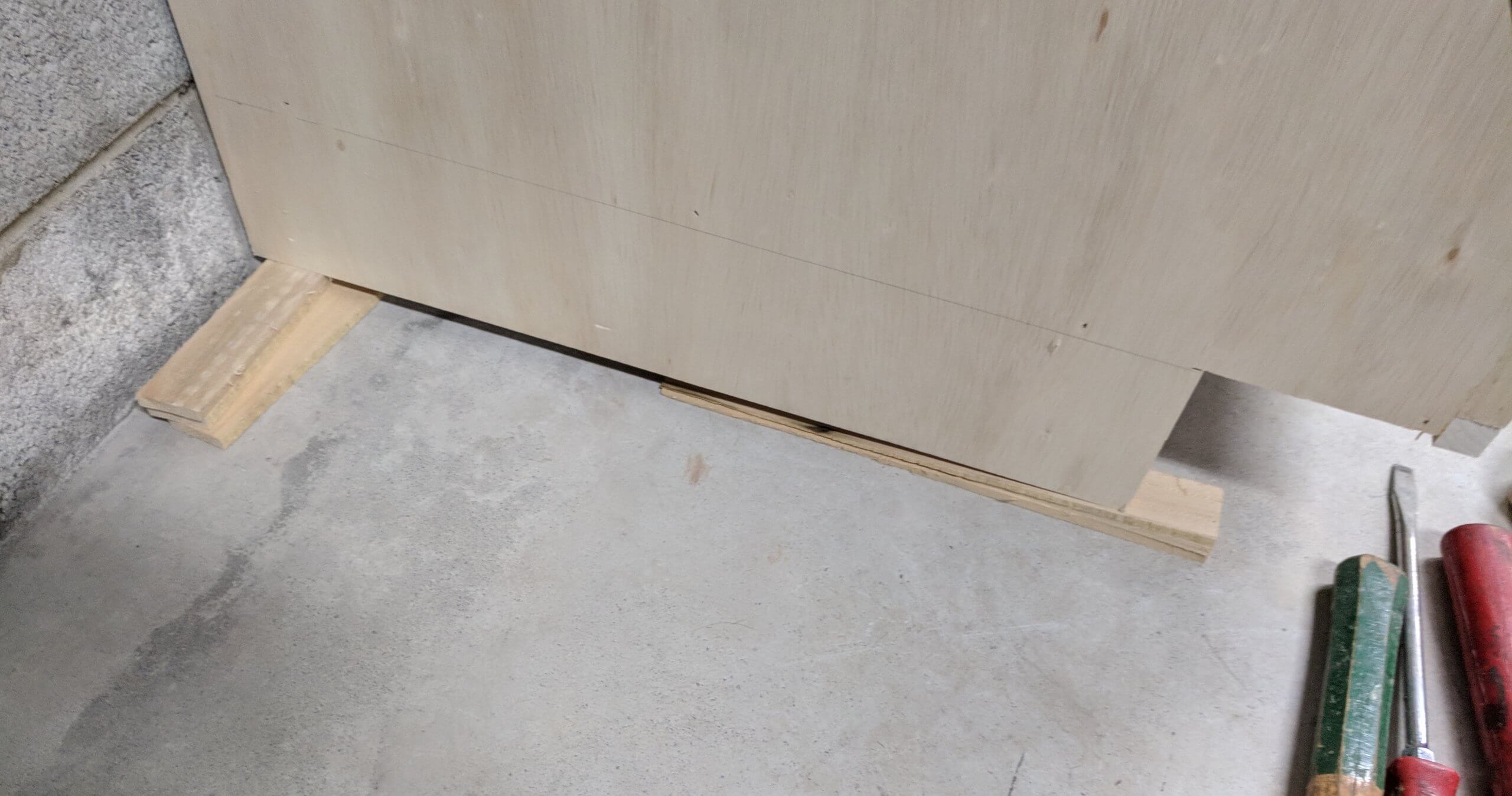
Once the first cabinet is leveled, you can mount it to the wall and place the adjacent cabinet with it, clamping securely so that they are square and aligned. Shim this cabinet just as the first, but using the “higher” starting point established by the first cabinet. You can see in the shimming image, the front of the right hand cabinet needed about 1/8 of an inch to obtain level front to back where as the front left of the left cabinet needed over 1/4″ to come in level line with the first cabinet. This is due to the floor sloping slightly away from the wall and slightly down from right to left.
Starting with the “high” side, and running a length of cabinet out ten feet will result in a modest rise. Don’t be afraid of the amount of shimming needed for the final cabinet. Level and plumb are essential.
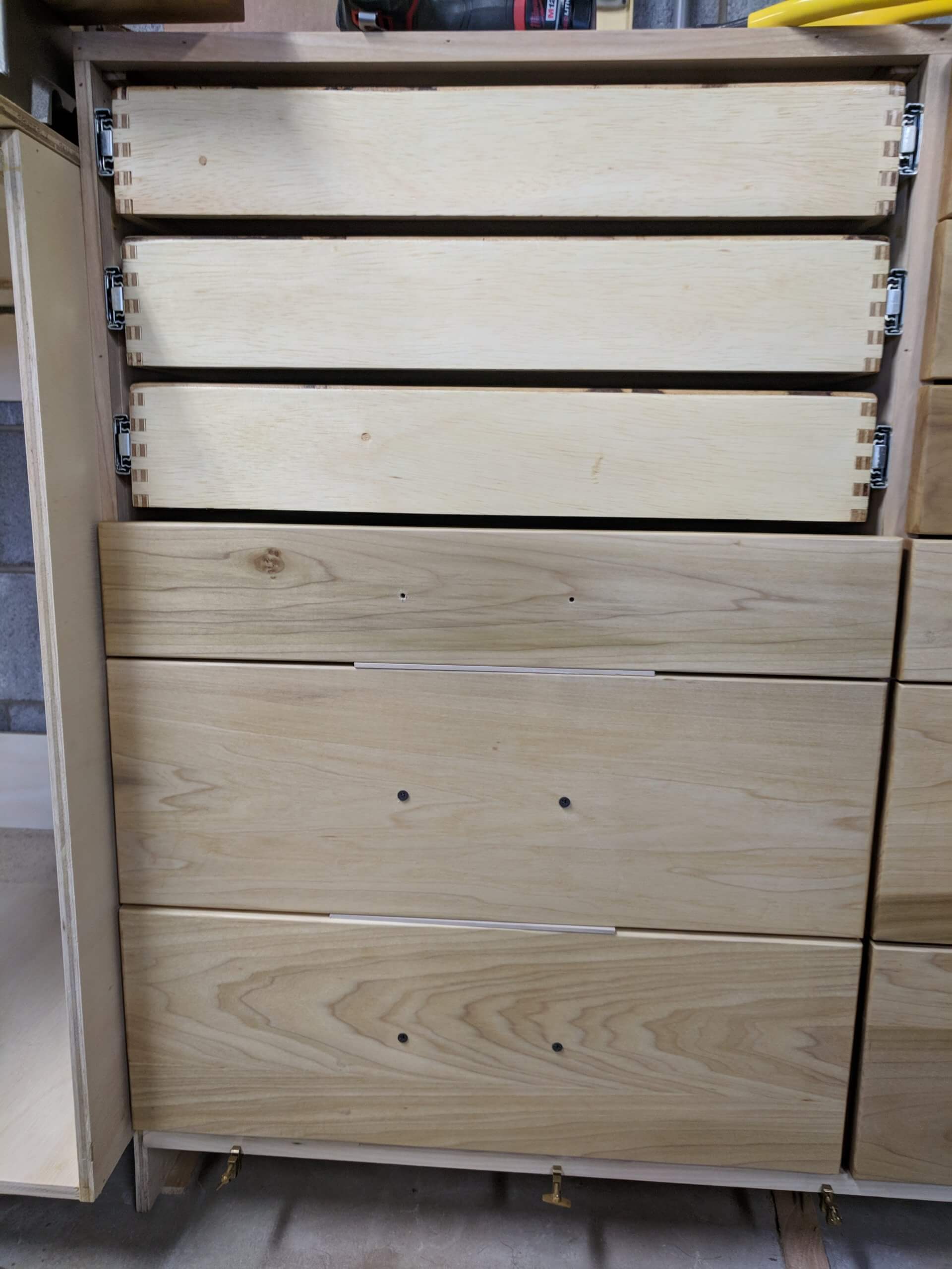
Note that in the image, the top back stringers have not been installed yet. This is a good time to install them if you are down with drawer finishing. I used them as shelves to hold drawers while they were drying.
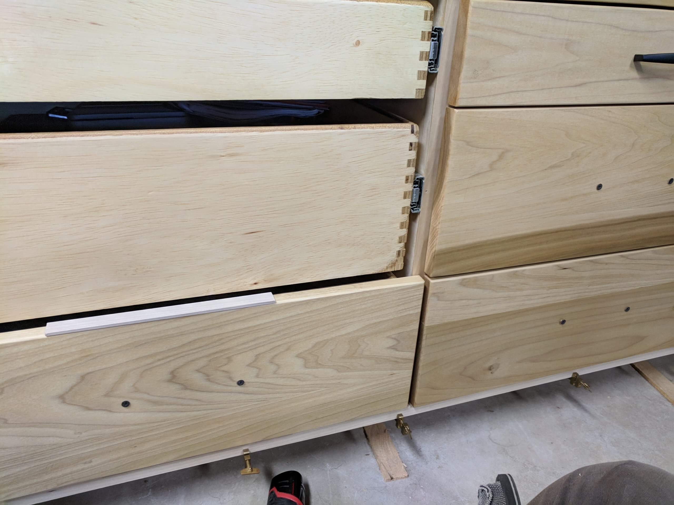
I left the slides protruding out 3/4″ with a plan to face the cabinets with wood. Any wood will work, even pine. Poplar is inexpensive in my area and that is what I will use for the cabinet face and the drawer fronts.
At this point in the installation the assumption is you have made the center cabinet. It is covered later, but is dependent on the dimensions of your saw.
I ripped out 1/2″ strips for the sides, a 1″ strip for the center and two 3/4″ strips for the top and bottom. They were installed with glue and brads, putting the top and bottom on first to join the two cabinets into one. After the top and bottom were installed, the vertical sections were cut to fit and installed the same way.
Once dry, sand with 120 to level any uneven joints and remove excess glue. Don’t worry about hitting the finish on the front face of the drawer as it will soon be covered.
The small drawers are 3 3/4″ tall and 22″ wide with a 1/2″ gap at each side and a 1/2″ gap between drawers. The drawer face should overlap 1/4″ on the outside face and 3/8″ on the inside face (the outside is faced with 1/2″ material and there is a 1″ facing where the two carcasses are joined) for a total extra width of 1 5/8″ (1/2″ on each side to cover the slides then 1/4″ on the outside edge and 3/8″ on the inside). Creating a 1/8″ gap between the drawers means that each draw extends into the 1/2″ space by 3/16″ (1/2″ – 1/8″ = 3/8″, 3/8″ / 2 = 3/16″). So each face will extend passed the drawer by 3/16 on the top and bottom for a total extra height of 3/8″. The target small drawer face is then 23 5/8″ X 4 1/8″.
The bottom drawers are 7 7/8″ by 22″ so with the added 1 5/8″ width and the 3/8″ height the face is 8 1/8″ X 23 5/8″.
You need 8 large drawer faces and 16 small drawer faces.
I used 5 1/2″ poplar lumber (6″ nominal) for the faces and had to glue up sections for the larger faces. After glue-up the large faces were ripped to 8 1/8″ then all drawer faces were sanded to 220 grit. While they were still unattached I applied four coats of Waterlox original (modified tung oil) and went over the finished pieces with #0000 steel wool (using rubbing lubricant), putting the same finish on the cabinet face. Once you have the faces completed, you can arrange them for grain and color that work well together and mark the back as to the draw bank and number.
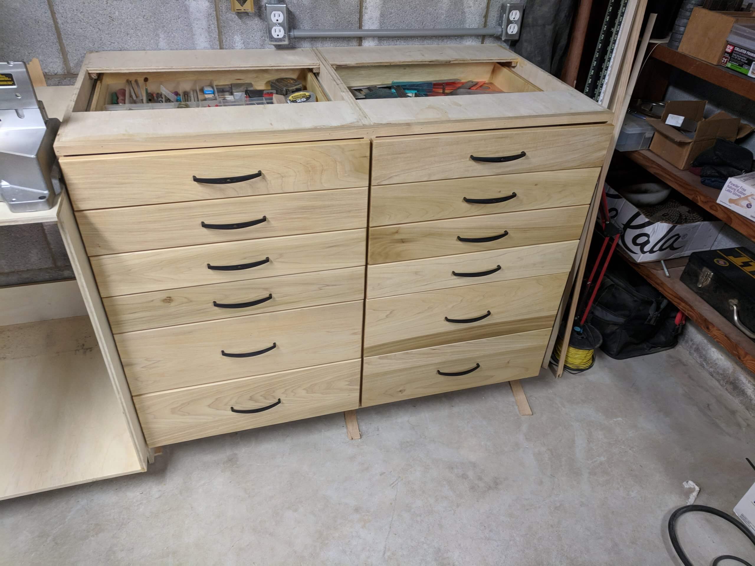
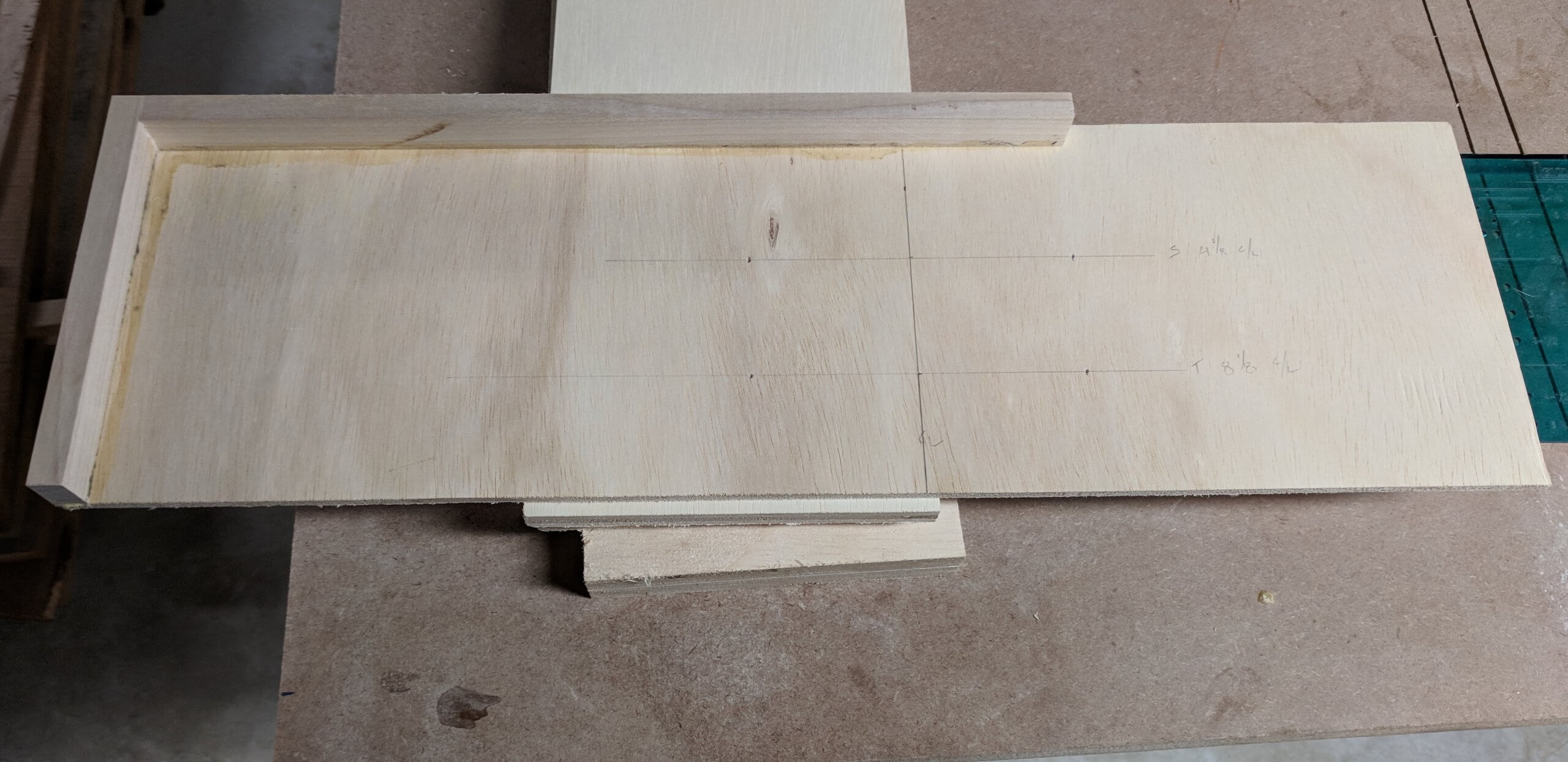
Drawer face attachment is straight forward. I made a simple jig to mark the location of the drawer pulls. It is just some scrap glued to a 1/4″ piece of plywood with the center line of the drawers marked along with the horizontal center of each size face and hole locations that are sized for the pulls I am using. Once marked, pre-drill holes in the drawer faces for the hardware you will use, pre-drill at least two holes in the small drawers and four in the larger drawers for screws that will go from the inside of the drawer and cut spacers the size of the your target spacing between faces (1/8″ in this case). The alignment of the first face is accomplished via a ledger clamped to the underside of the cabinet. Place the first drawer face on the ledger, then a spacer, then repeat for all faces to be certain that the spacing is accurate all the way up the cabinet. Use a square to establish that the drawer faces are the same distance in from the edge of the cabinet. When satisfied, drive two screws through the hardware mounting holes to temporarily attach the face to the drawer, then open the drawer and permanently screw the face the drawer. Keep in mind the material thickness you are working with and pick your screw lengths accordingly. I am using 3/4″ faces and 1/2″ drawers so a 1″ screw will work.
Tops are a matter of personal preference, but I am using 3/4″ MDF because I want a flat dimensionally stable surface. To increase the toughness of the MDF I am edging it with poplar. The edge thickness is determined by the space available by the saw. I made my left top 28 1/2″, the center top 30″ and the right top 26″ deep. The left is deeper to allow for more room in front of the fence.
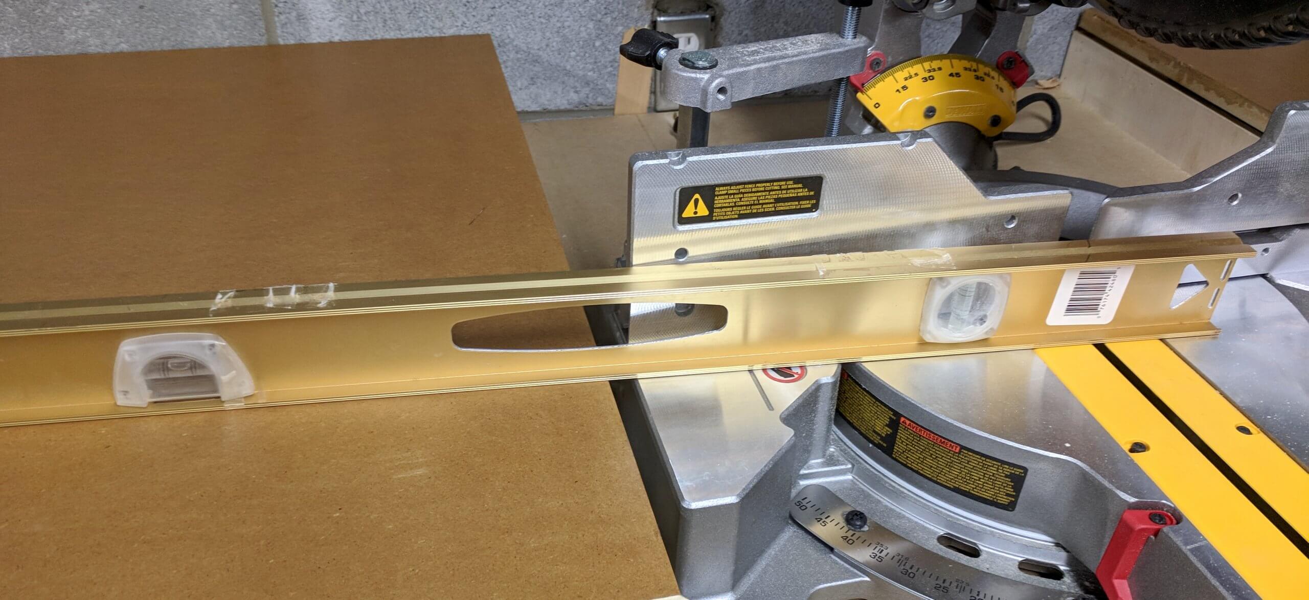
There may be slight irregularities in the cabinets that create differences in height. Prior to locking down the counter tops you want to verify that they are at the exact same height, so that lumber your are cross cutting on the saw is held at the same angle and level on the left and right top extension. You will shim the counter top much like you shimmed the cabinets. You want to start with the highest unit. In my case the right cabinet was 1/16″ lower than the left, so I shimmed the right counter top up to level with the left counter top. You can “try” to avoid this step by mounting the left, right and center cabinet at the same time, but I had to mount my right cabinet first to use for storage as I was replacing a similar unit. In practice it will not be avoidable as you are making a ten foot run of cabinets over uneven flooring.
The process is start with a level counter top on the highest unit, then level the other counter top in line with the first. Finally level the center so that the saw sits perfectly level with each side. To accomplish this you use shims between the top and the stringers, tapping them in and checking for level and alignment. Take you time at this step as the function of the miter saw station will be impacted if the feed surfaces are not on the same plane as the miter saw surface. Note that you will likely not get it perfect and the feed surfaces will generally be used for length setting and you will still index your cut off of the miter saw table (the metal portion).
I finished the MDF with two coats of polyurethane.
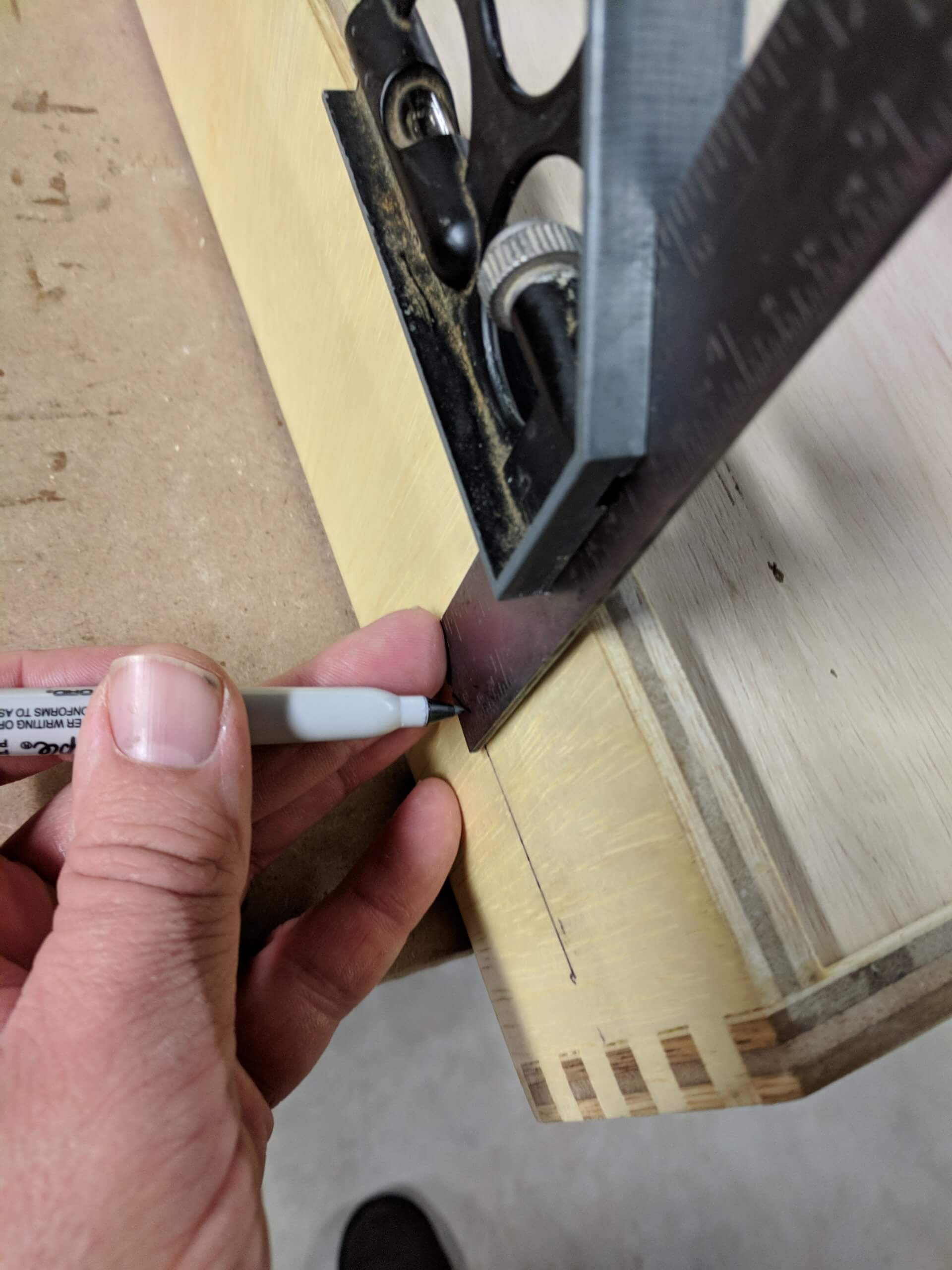
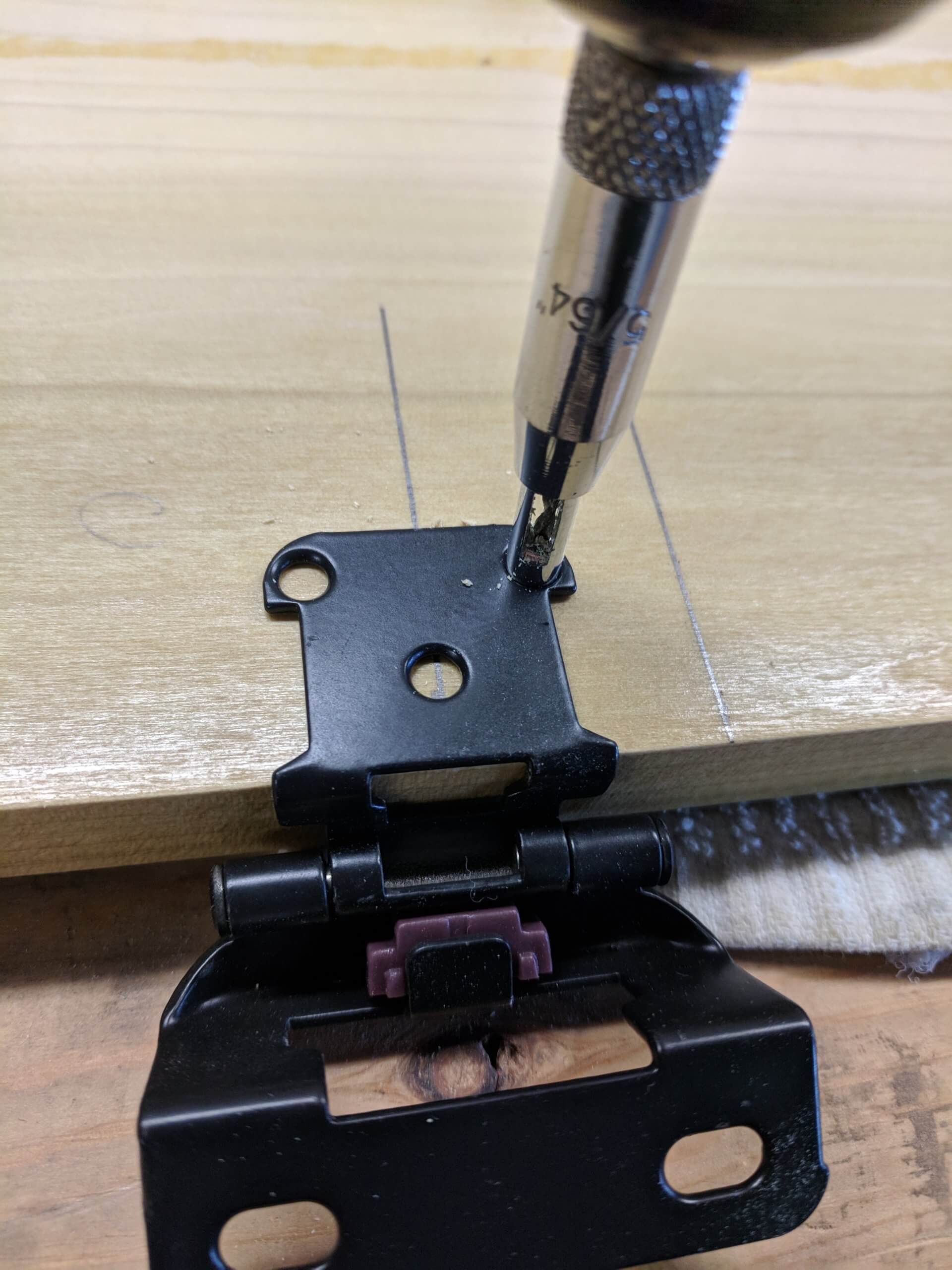
Door mounting on the center unit is simple as I used basic overlay hinges (vs complex European ones). I marked 1/4 of the way up from the bottom and down from the top and made a line with a square. I held the hinge on centered on this line and drilled the holes with a self centering bit (not essential, but nice to have) and attached the hinges to the door.
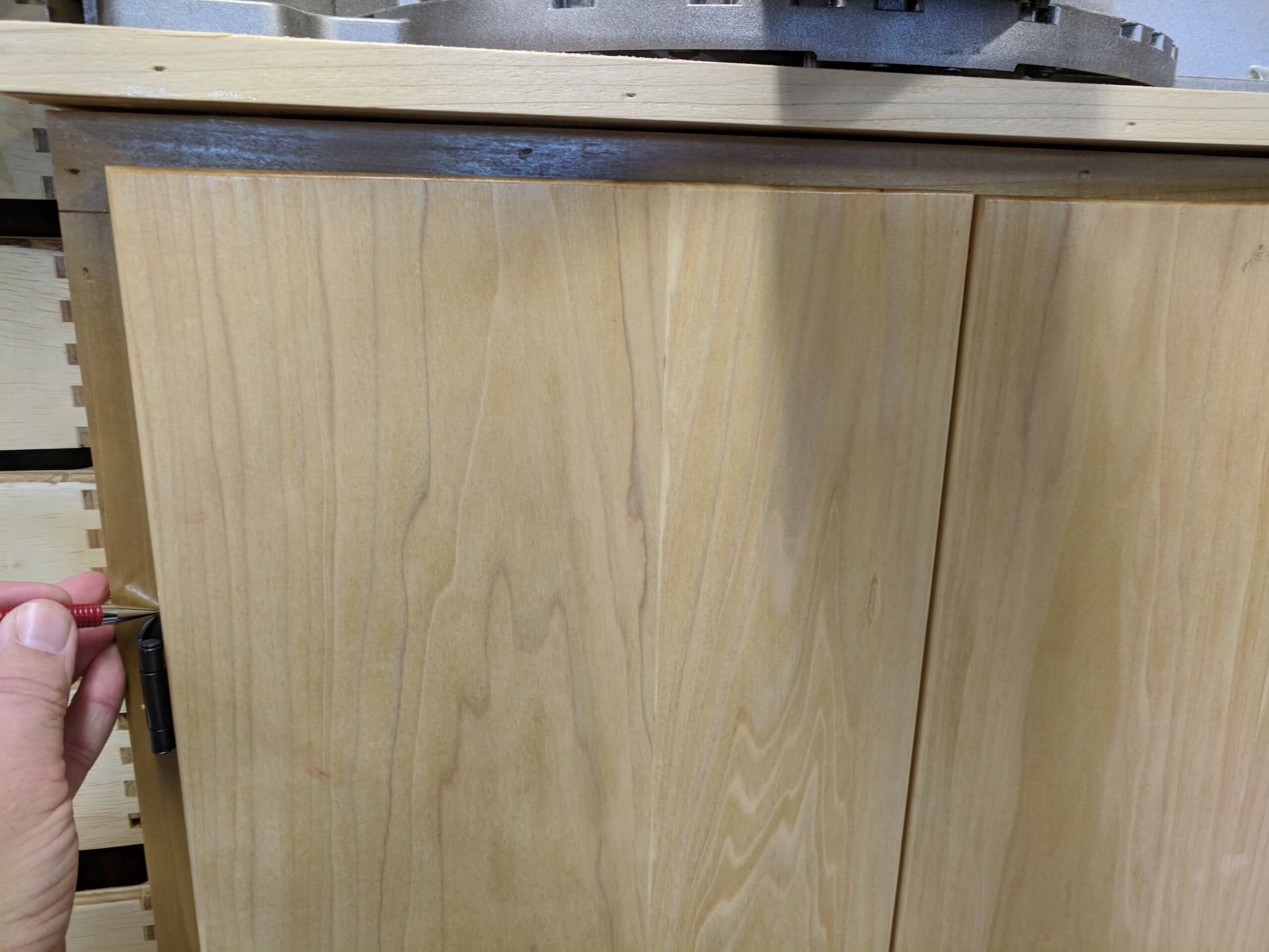
I aligned the door to the cabinet with an equal overlay on the top and bottom and drilled for the hinge mount on the style of the face frame, being careful to hit the center of the oval slot to allow for adjustment. After the first door was mounted, I held the second up to the same level, marked where the hinge would be and mounted it the same, but not firmly. I closed the second door and pushed it to align it with the first door then tightened down the hinge. In all of these, use hand tools and not a drill/driver as they are very small fasteners.
Fence
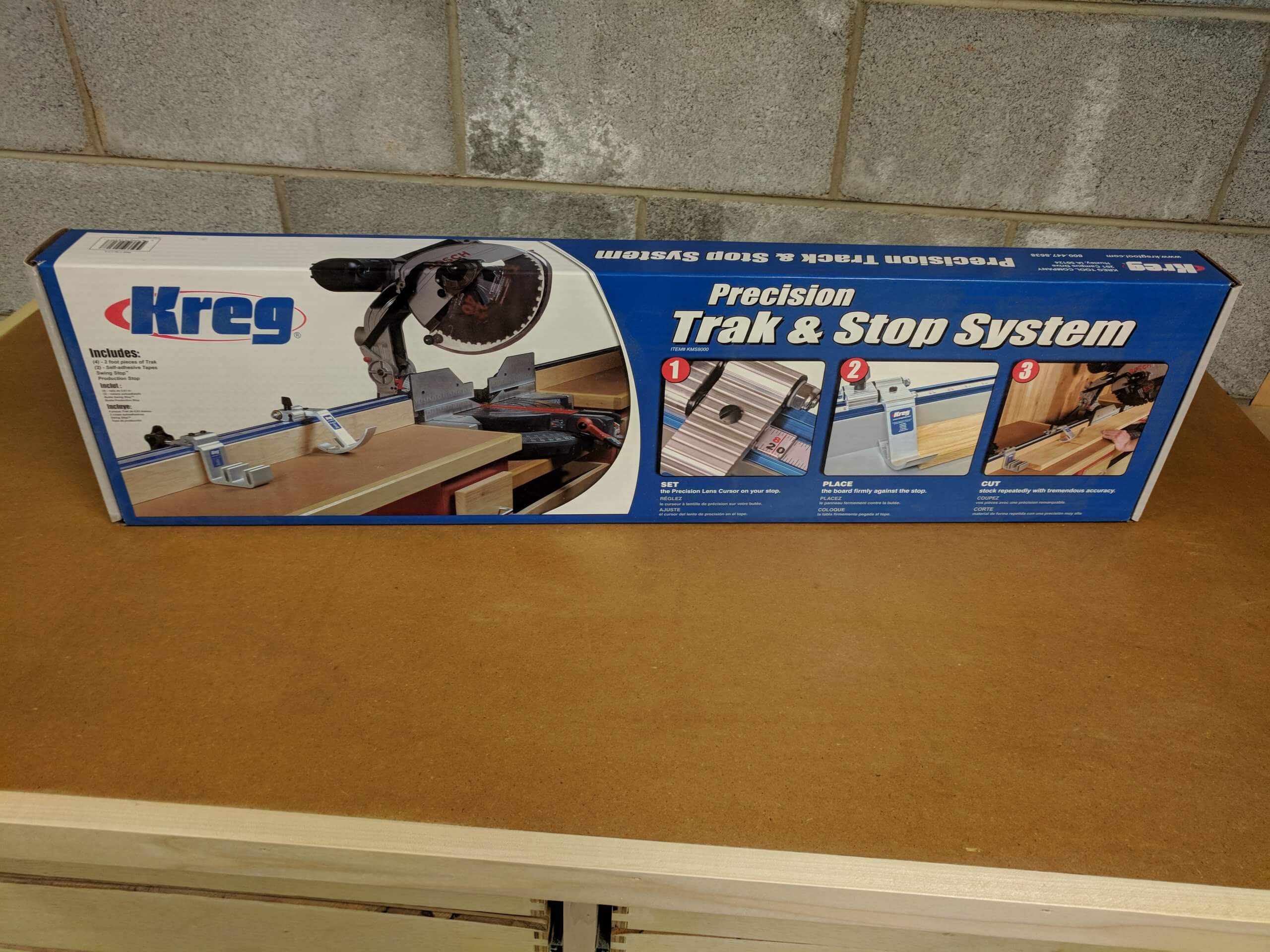
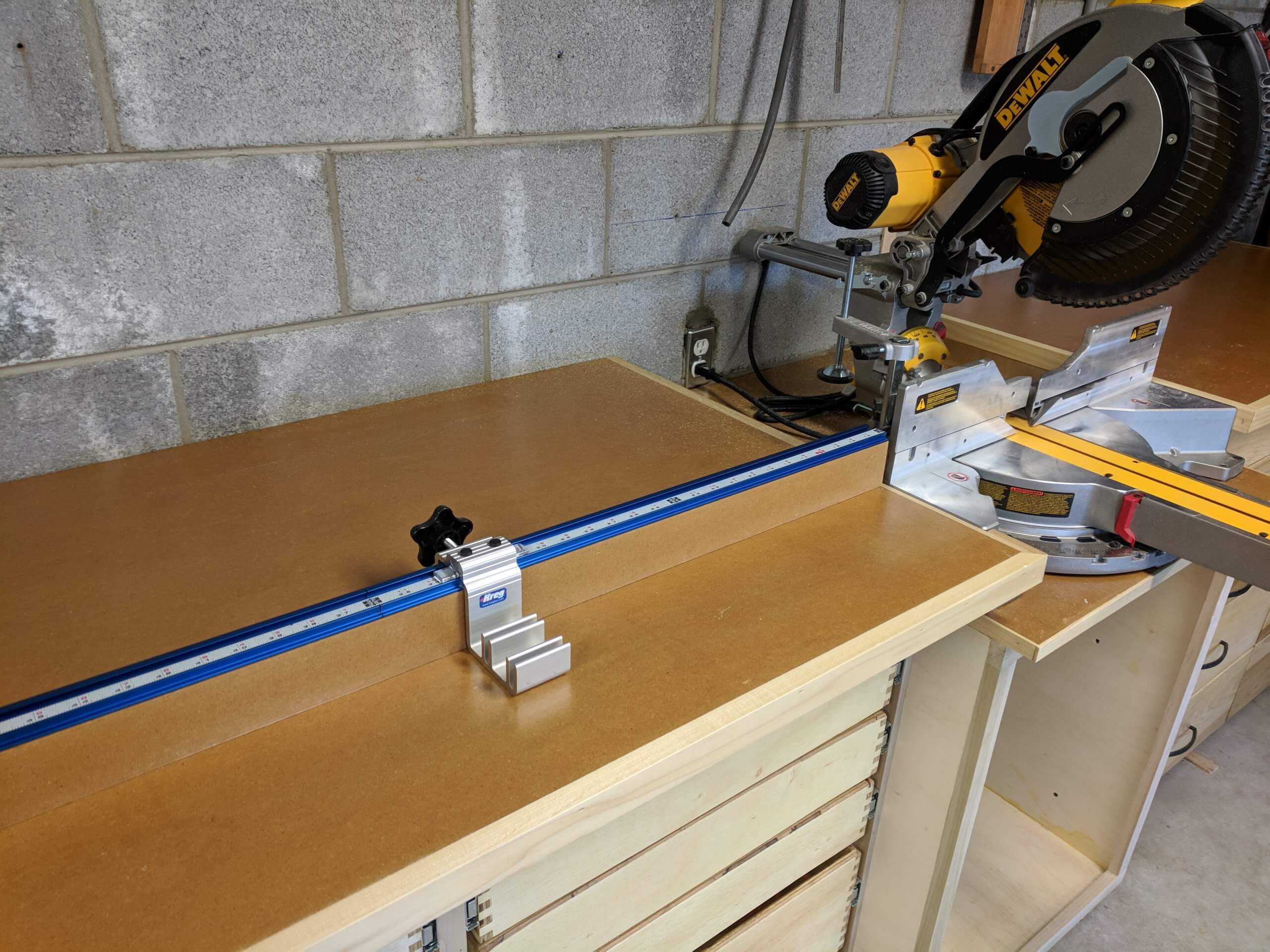
Rather than fabricate a stock holding or measuring system, I purchased the Kreg “Trak & Stop System” to use as the basis of the table fence.
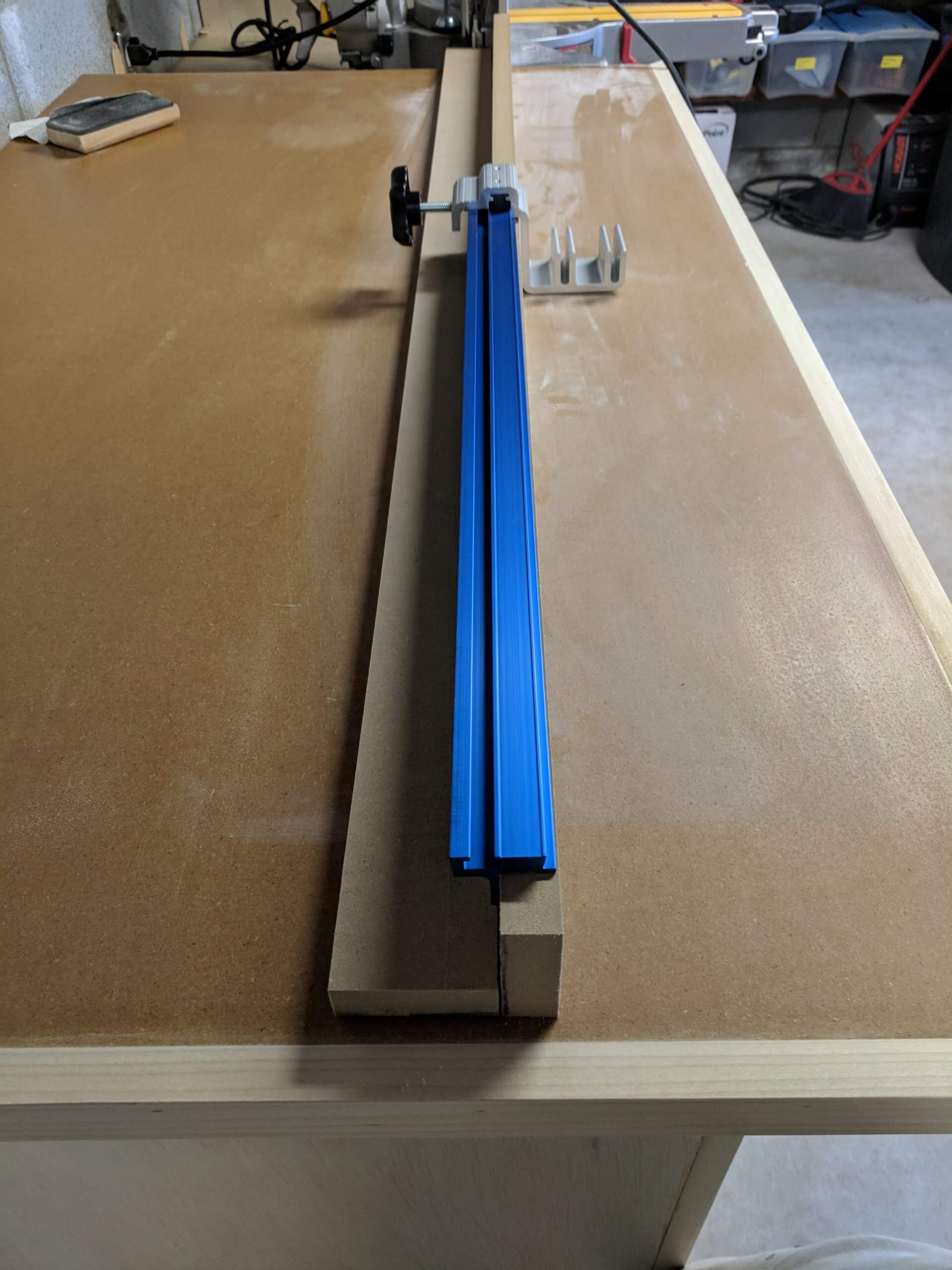
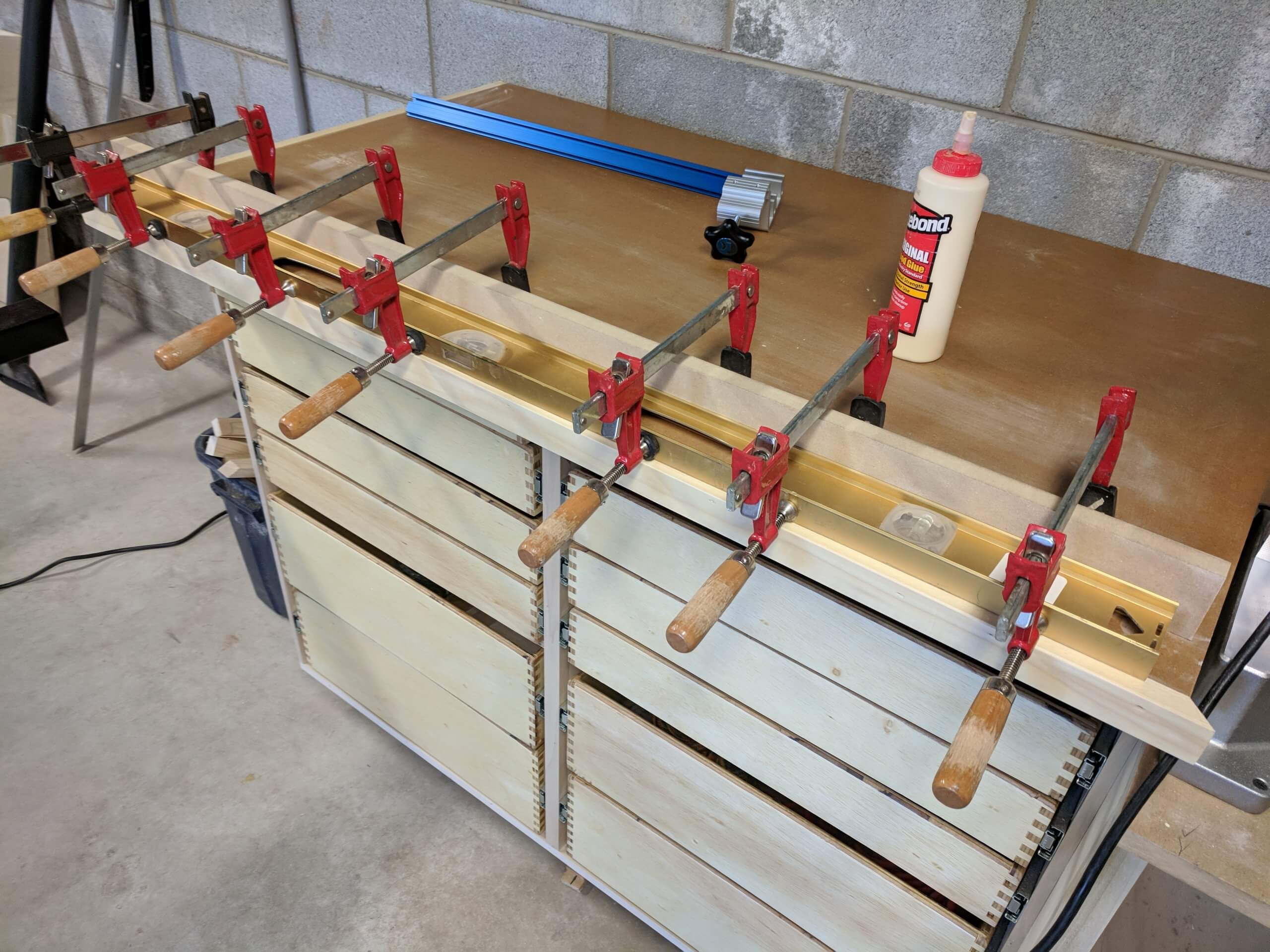
The kit requires you to make your own fence and has reasonable instructions. The core measurement is that the fence needs to be 2 1/4″ high (from the work surface). I simply ripped out two 2 1/4″ X 4′ strips from leftover 3/4″ MDF used for the counter tops. I glued them at a 90 degree angle and applied two coats of polyurethane. To ensure a straight resulting fence face I used a straight edge as part of the glue-up.
The kit comes with enough “Trak” to create 8 feet of fence. I only setup 4′ on the left of the saw. You have to pre-drill for the mounting screws.
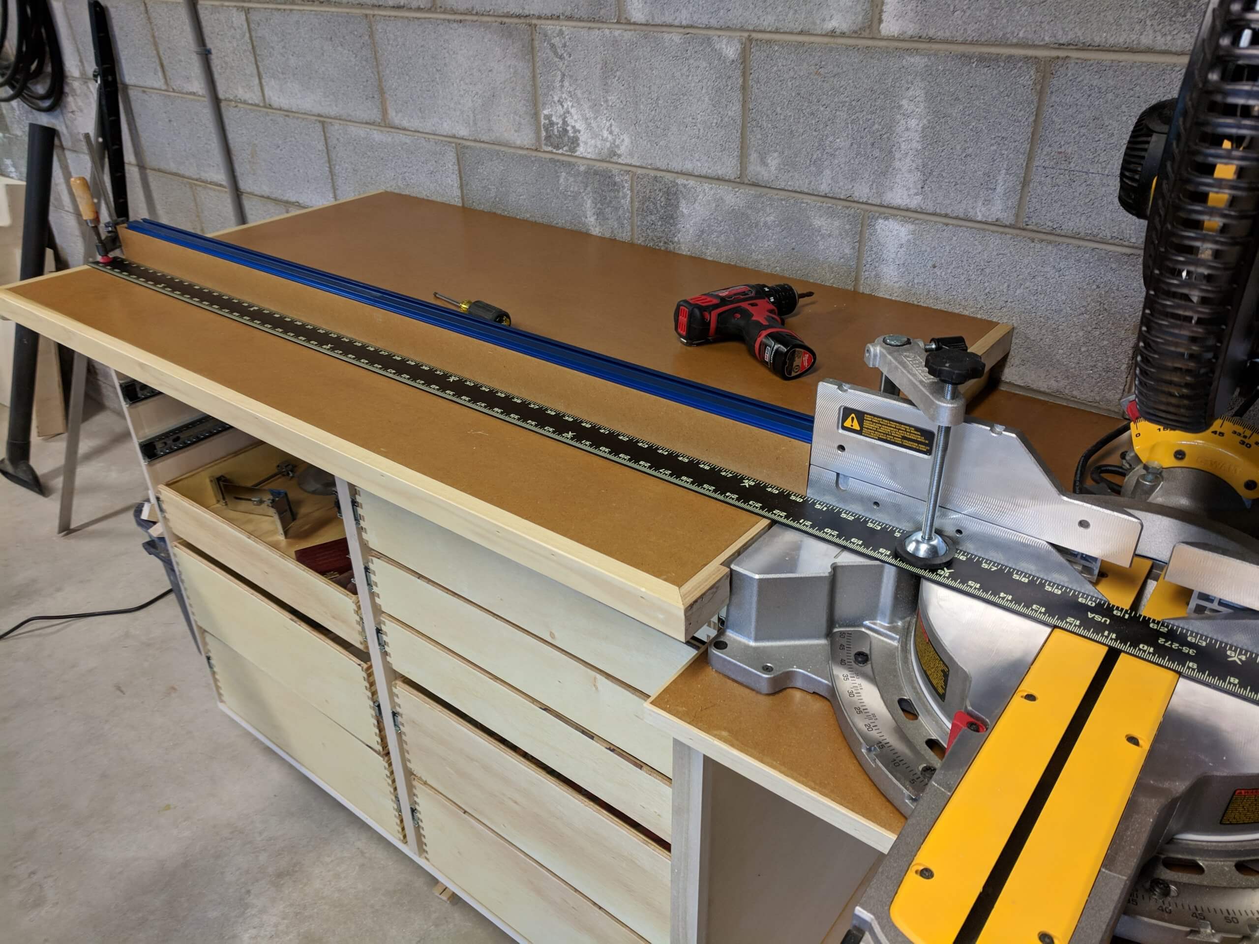
Once attached the fence is screwed into place with 1 1/2″ screws driven through pre-drilled and counter sunk holes into the counter top while position with a straight edge true to the miter saw fence.
The peel and stick tape measure is applied using the same procedure as any shop equipment: cut a piece, measure, mark where the indicator falls on the rail with the stop touching the piece you cut, apply the tape with the measurement of the piece at the mark then use the fence and stop to cut another piece and use the micro adjustment of the indicator to dial into the measured length of the second piece.
Mistakes I made or things I would change: I ended up trimming 1/2″ off the top of the higher of the the larger drawers and 1/2″ off the top of top smaller drawers. The larger were trimmed to make room for another stringer as some of my 1/2″ plywood had a bow in it I needed to address. The top drawers were cut down as I used a cleat that was thicker then required. I also hand to fit the wood facing on the side of the counter top around the saw (you can see it in one of the fence images). I should have made the base cabinet wider to allow for counter top edging. Though I mentioned it in the write up, the right carcass was about a 1/16″ lower than the left as I did not install them at the same time. Were I to do it over, I would have installed all three base units at the same time to help with leveling. I also found that the finger joints were a bit tighter than ideal and I would probably give them a bit more room next time. If I were doing it again I would use a poly oil (oil wax) for the finish vs the tung oil, but I mainly did the tung oil to experiment with the finish. The hand rubbed Waterlox is a fantastic finish, but a bit labor intensive for such a “work oriented” project. Finally, I would increase the width of the top and bottom carcass facing (fake face frame) by 1/2 as there is no real overlay by the draw fronts. It is not noticeable, but another half inch at the top and bottom would complete the cabinet better.
Hi Jervin, any chance of getting the sketchup files for the Miter Table please, the link is not working. Thanks in advance.
Let me look at the link. If not, I can email you.