
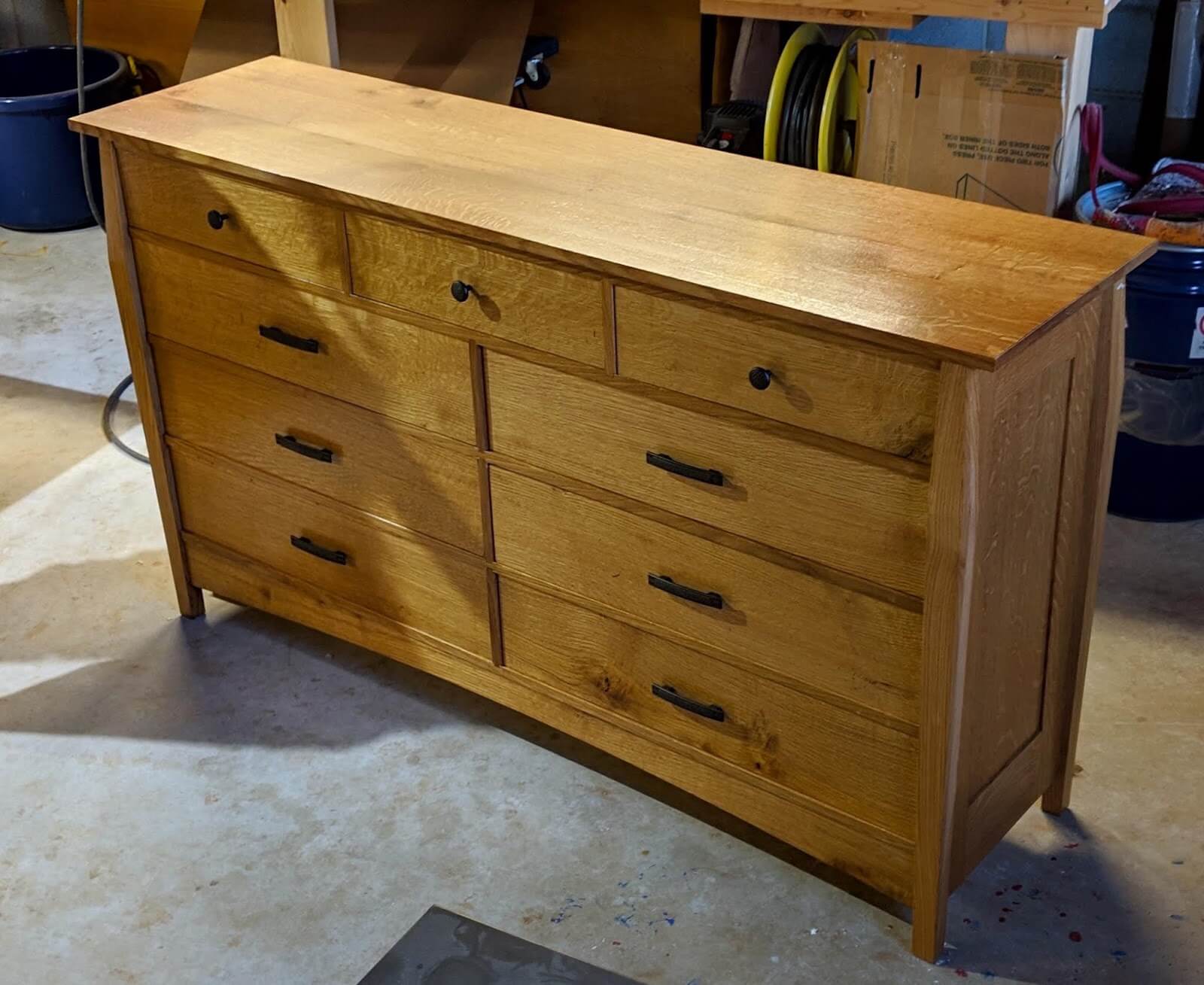
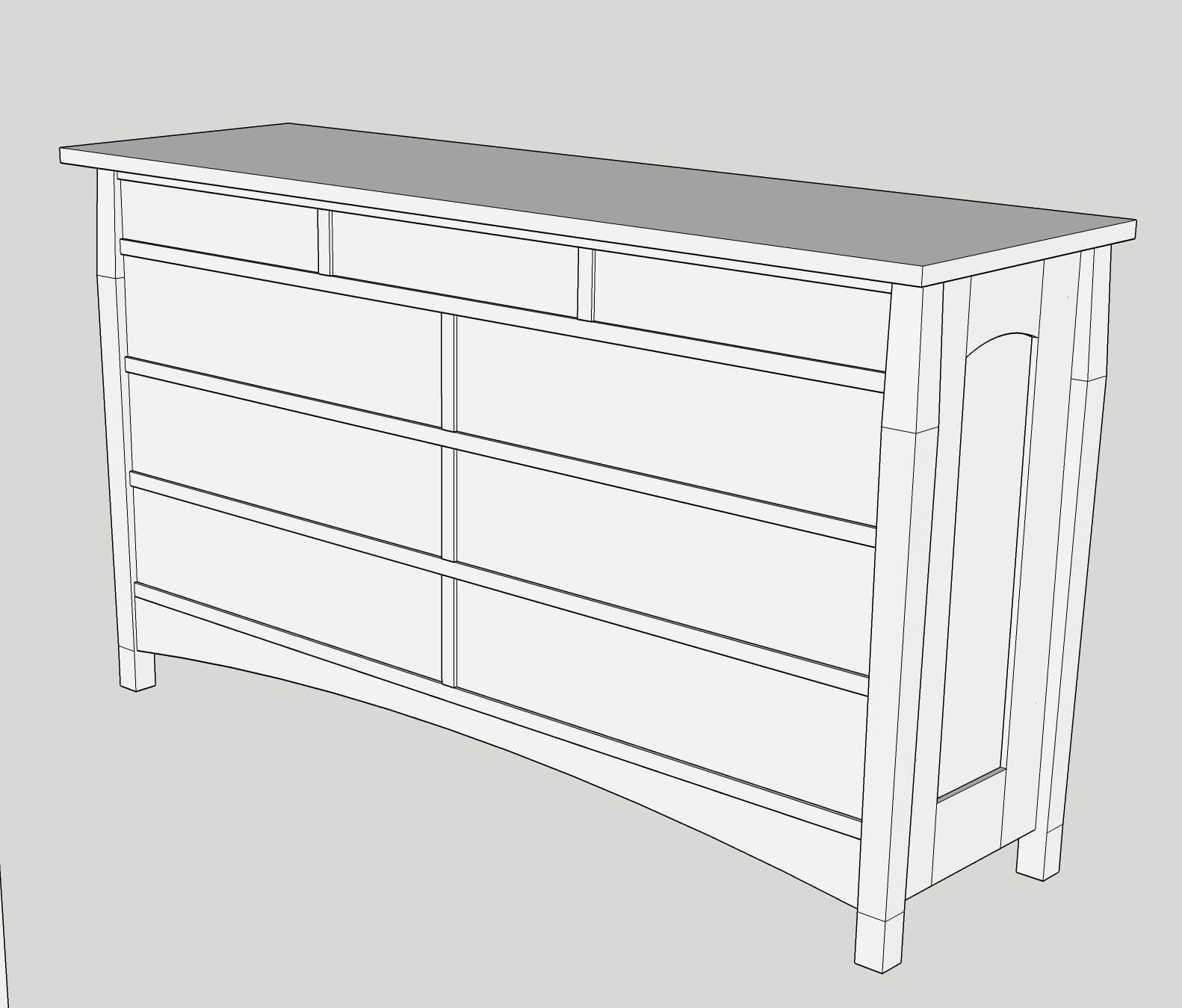
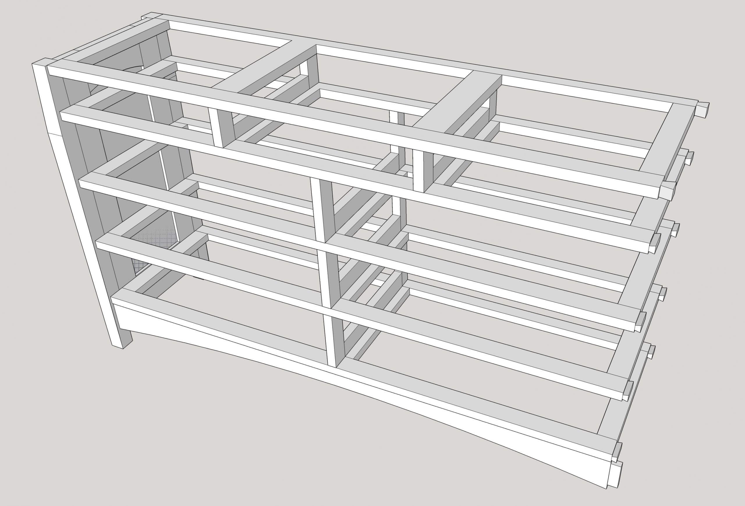
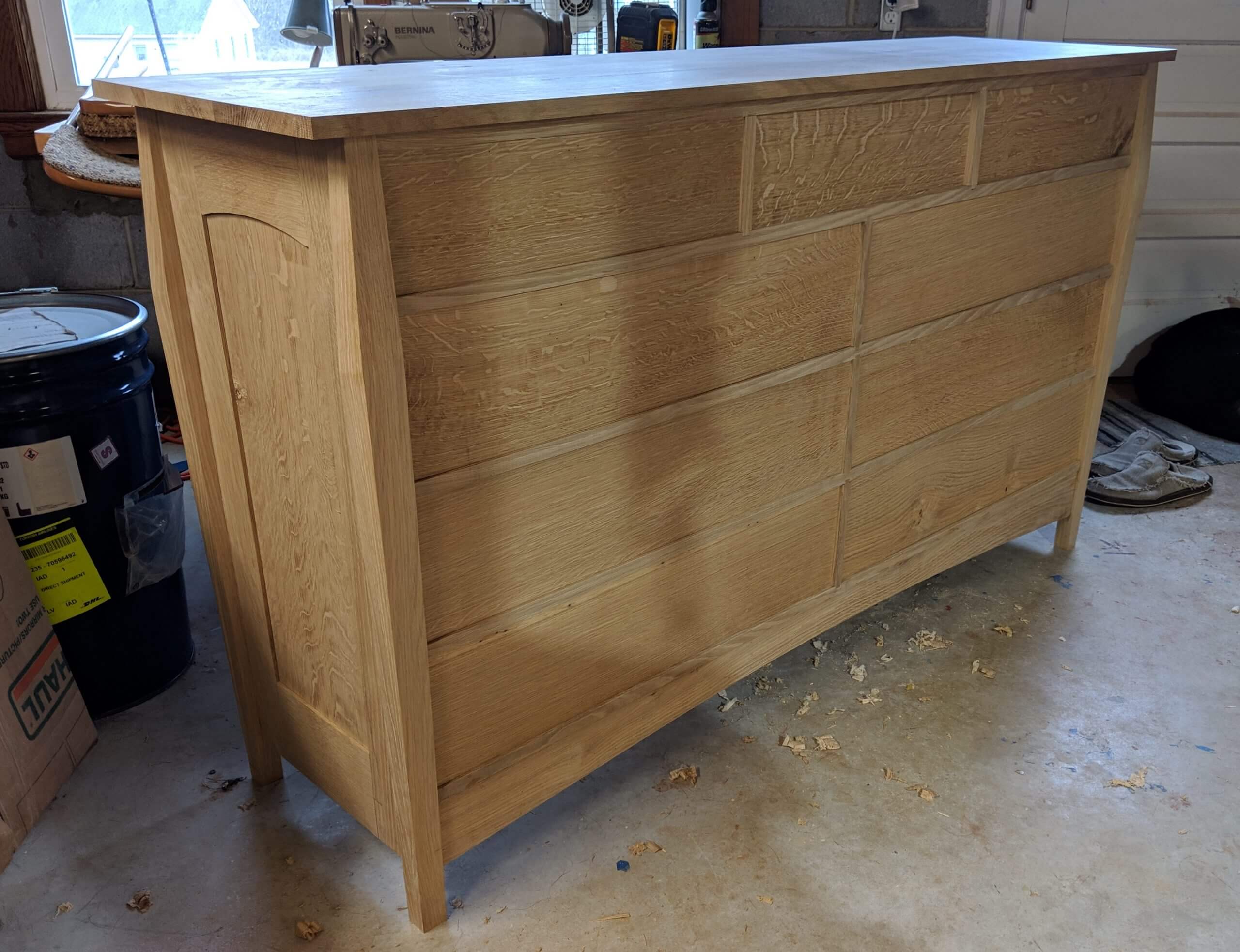
This piece follows the lines of standard Arts and Crafts bedroom furniture, double tapered legs, a panel design with arched top rails and an arched lower stretcher (similar design elements to the night stands).
It deviates in a few areas. First it is a low/wide style of dresser and it also has a Drawer Web (Drawer Divider and Drawer Runners) above the top set of drawers. Traditional pieces were the standard tall dresser and they often omitted a top Drawer Divider. Over time the tops often bowed and the addition of a top support web will combat this. wanted a bookcase and had an aesthetic that was very different than mine. Step one was to come up with a design that was suitable and for this I used simple marquetry to add interest and variety. 90% of what I make is Mission Style or similar so this was a bit of a departure.
It is approximately 65″ wide, 19″ deep and 38″ tall. I say “approximately” as the finished size is variable based on how the stock mills out. For example, the design calls for 2″ X 2″ leg stock, but I laminated up two milled 4/4 boards and ended up getting 1 7/8″ when the dust settled. Cabinetry often has to be an exact size, furniture can vary slightly and rather scrap legs that came out to be 1/8″ short of a figure that was generally arbitrary to start with, the idea is to be flexible. When milling the lumber for the top, I found a fantastic board that would be perfect for the top, but I could only get two 66″ boards out of it, so when making the Drawer Webs to connect the two end panels, I adjusted them down one inch versus sticking to a 65″ width and needing a 67″ top. These are just examples of small decisions that you can make if you are flexible. In many ways it is letting the wood guide you. If you can get an amazing part out of some stock, but that requires a small change in design…make it.
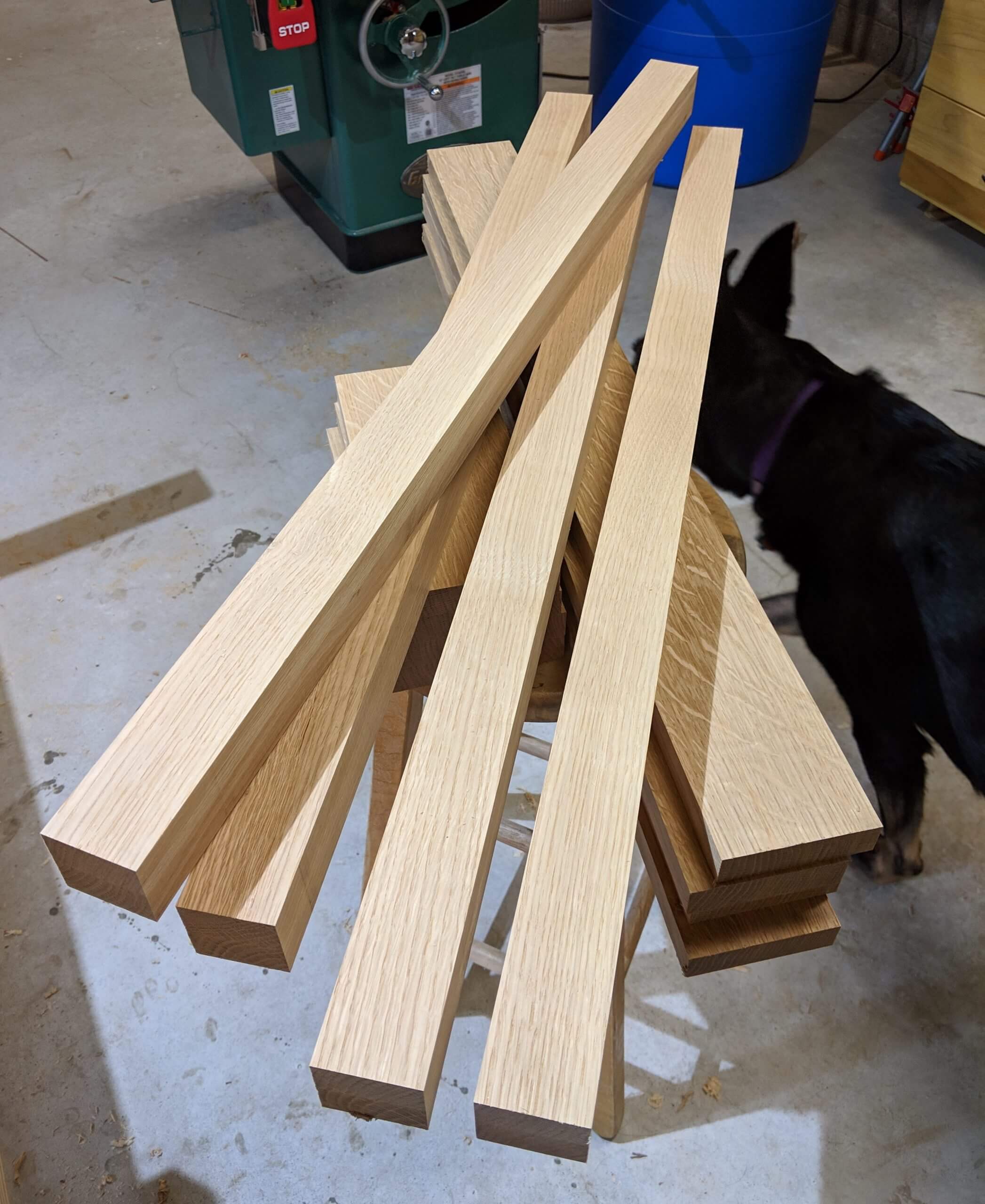
Legs
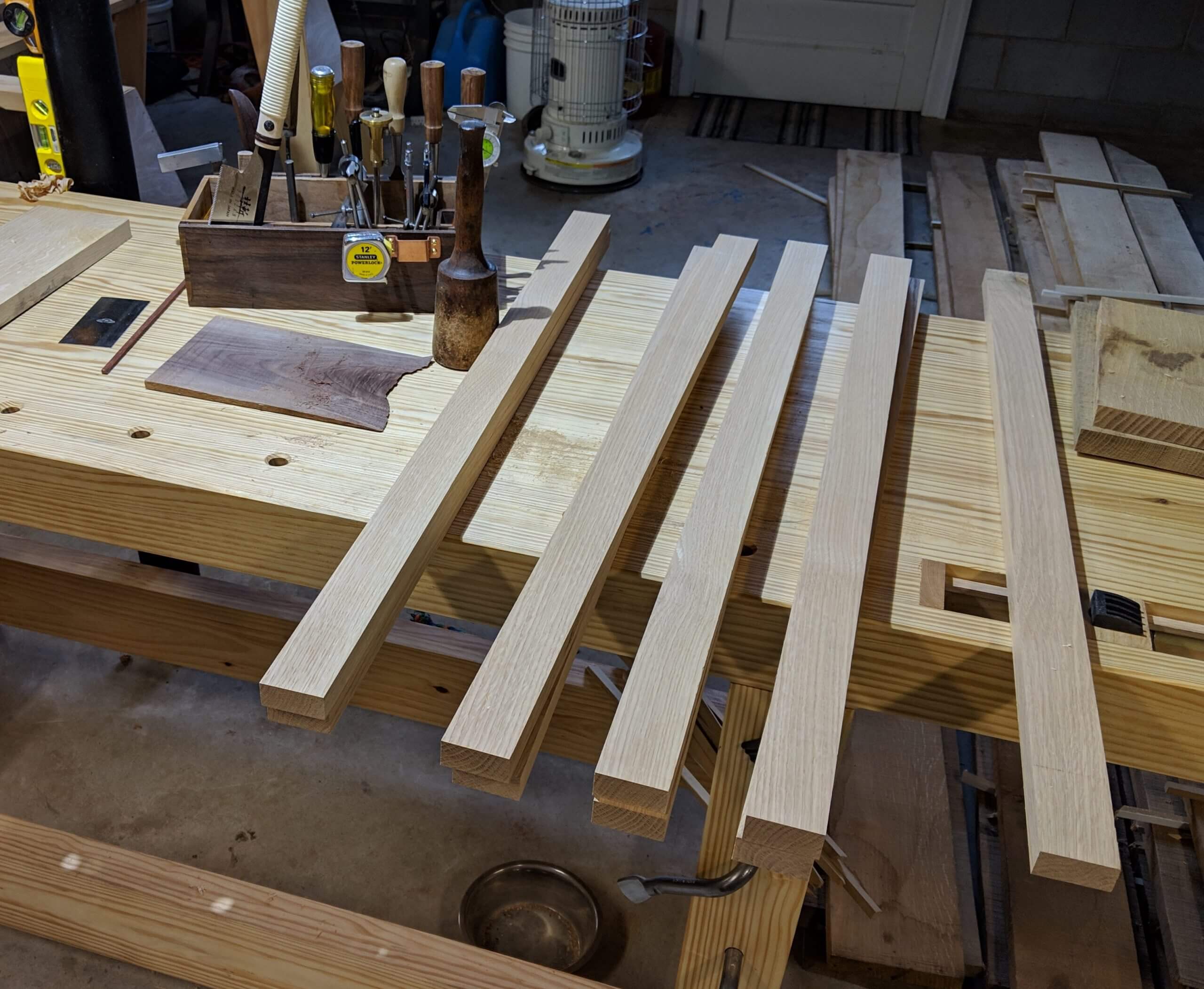
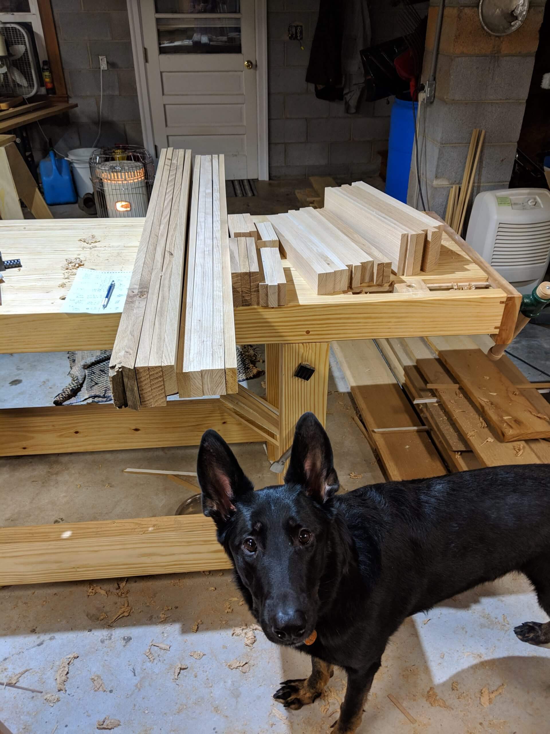
If you have 8/4 stock, great, but if not don’t be shy about making some. I cut and milled 4/4 stock then glued up two to make a leg. I did take them from one board so each leg would be comprised of two parts with approximately matching grain. I cut and milled 4/4 stock then glued up two to make a leg. I did take them from one board so each leg would be comprised of two parts with approximately matching grain.
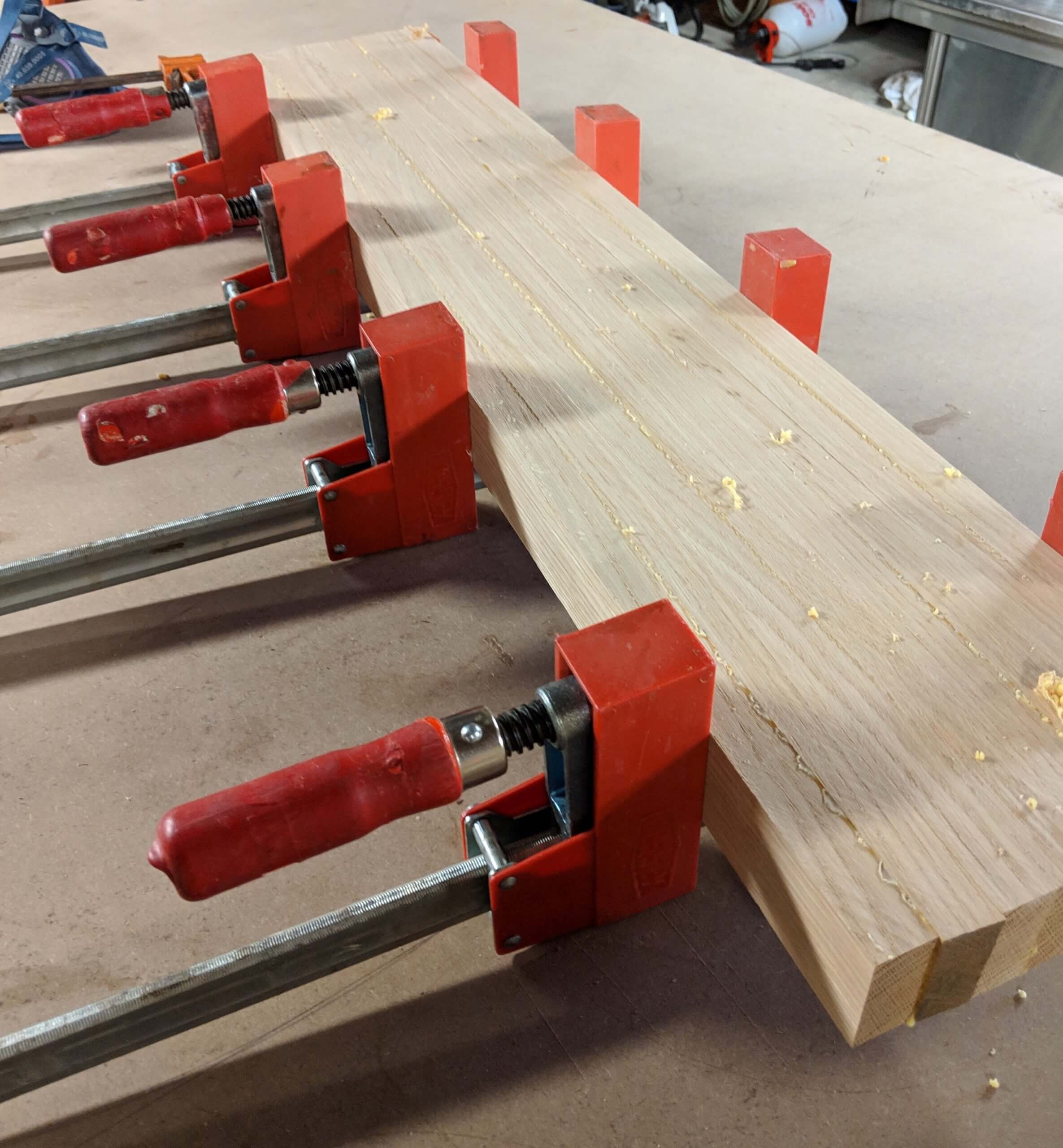
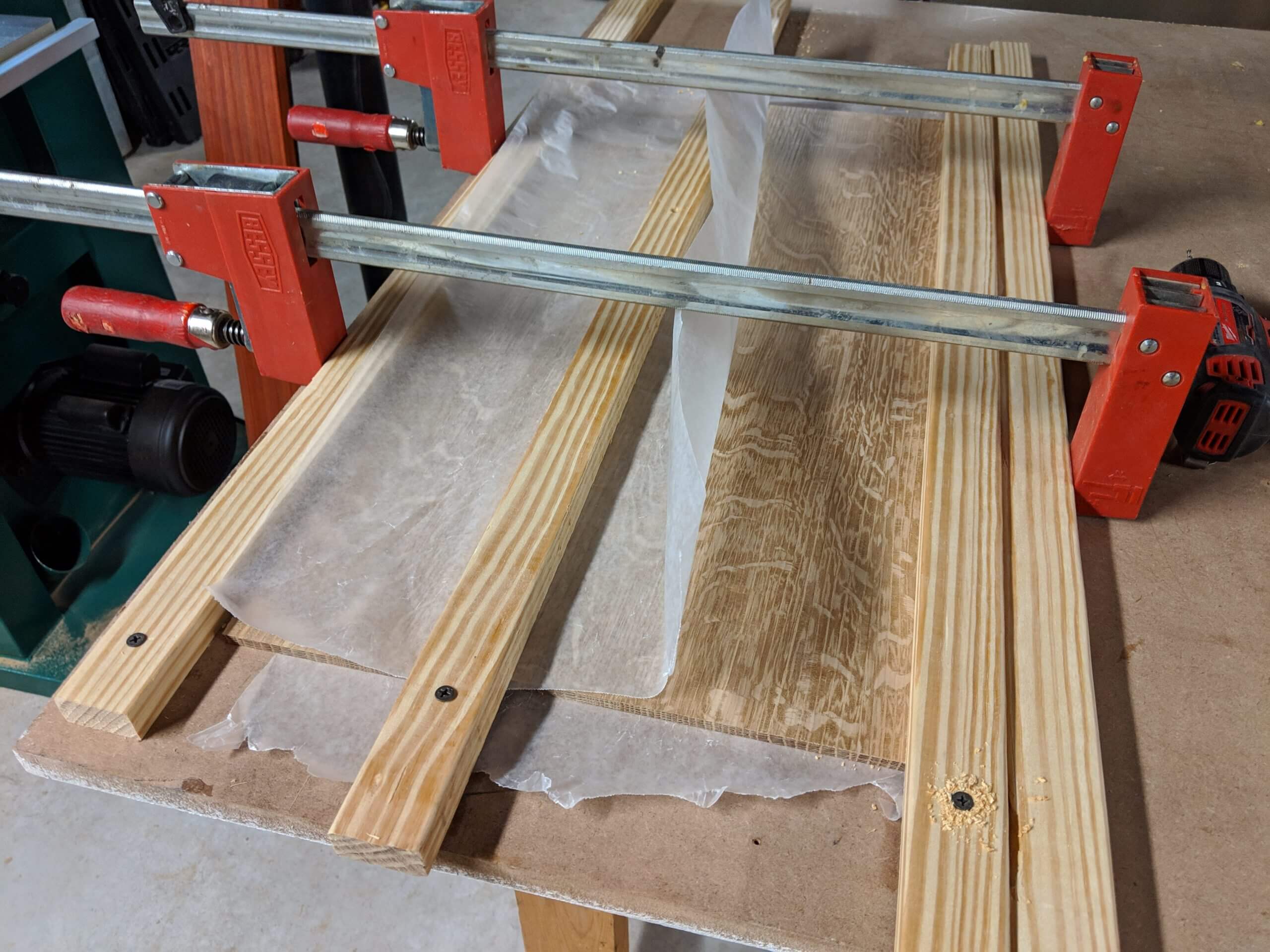
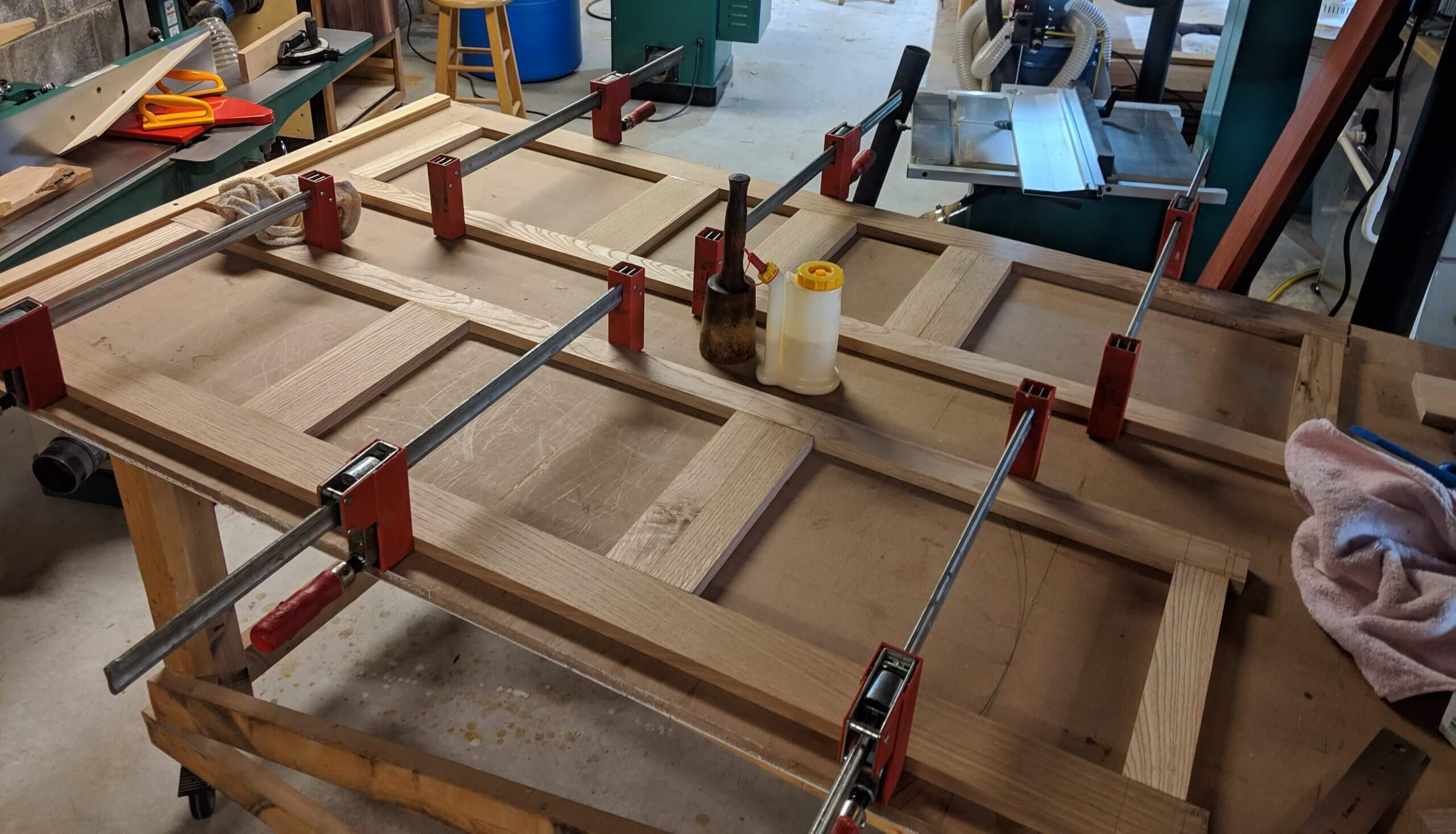
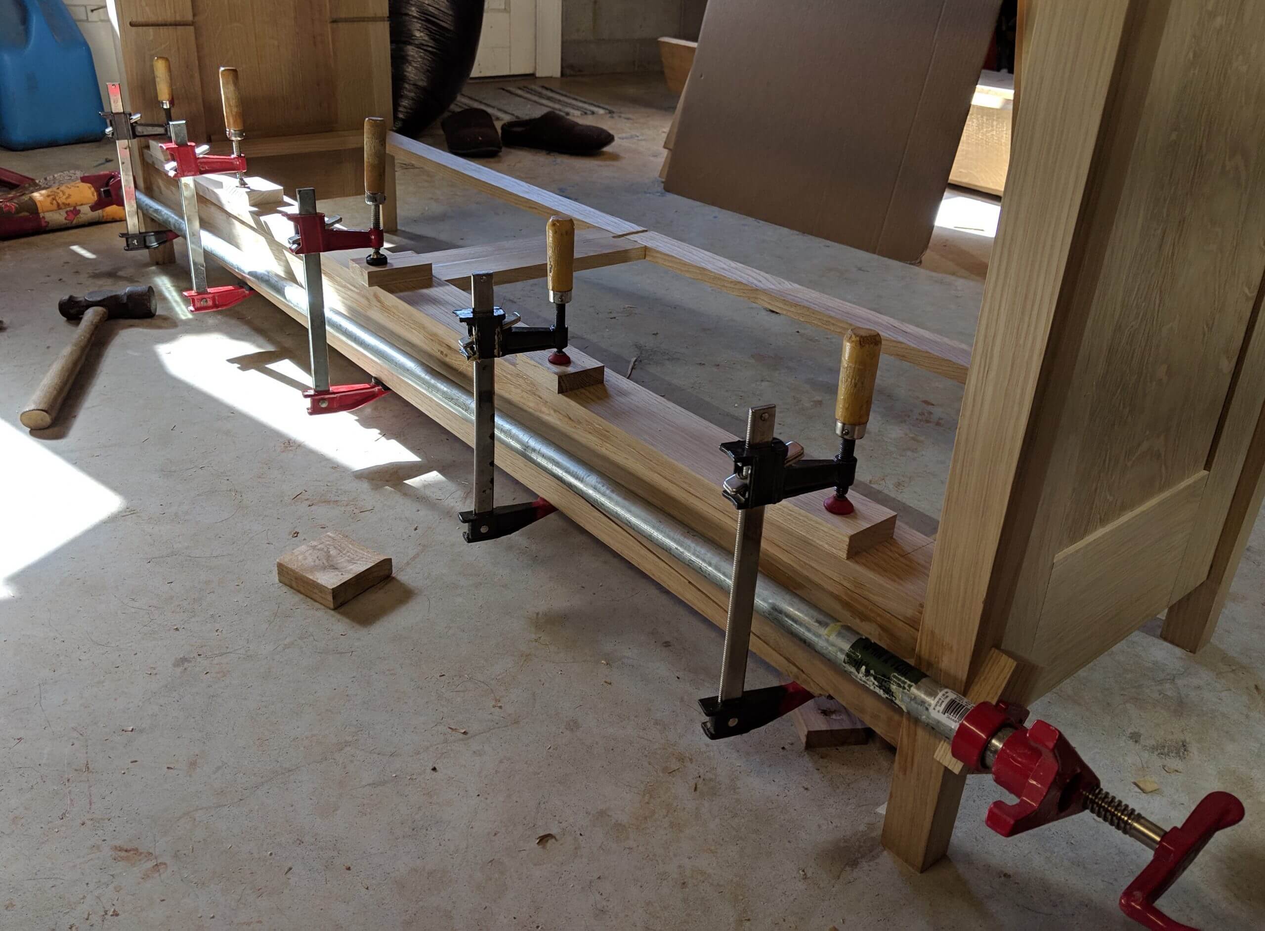
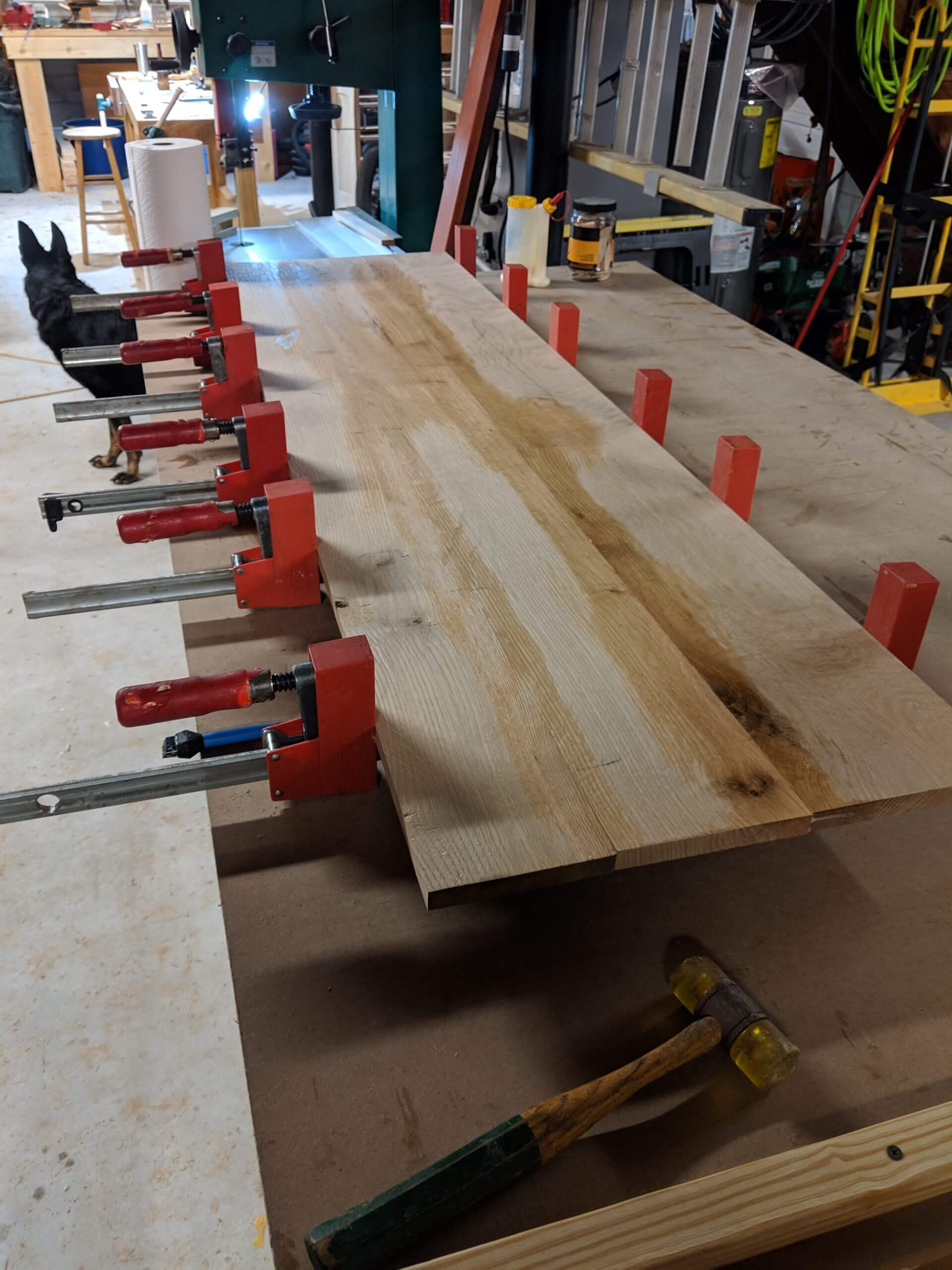
Legs are gang glued, putting all eight parts into the clamps at once with ample glue. After the glue sets the hard bits are scraped off with a scraper and the legs are jointed then planned as a unit. Square is ideal, so run them through the planer on each side, but if you end up with a slight rectangle it will be generally unnoticeable under 1/8″ as long as your orient them all the same.
The first dimension limiting action is cutting the legs to length. I cut mine to 37″. All other parts will be made based on this size, so if you want a taller dresser or a shorter dresser, now is the time! The legs need a double taper, a mortise for the center stretcher and a slot to accept the long tenon to be cut on the side of the stile. Each of these operations are best done when the panel is under construction.
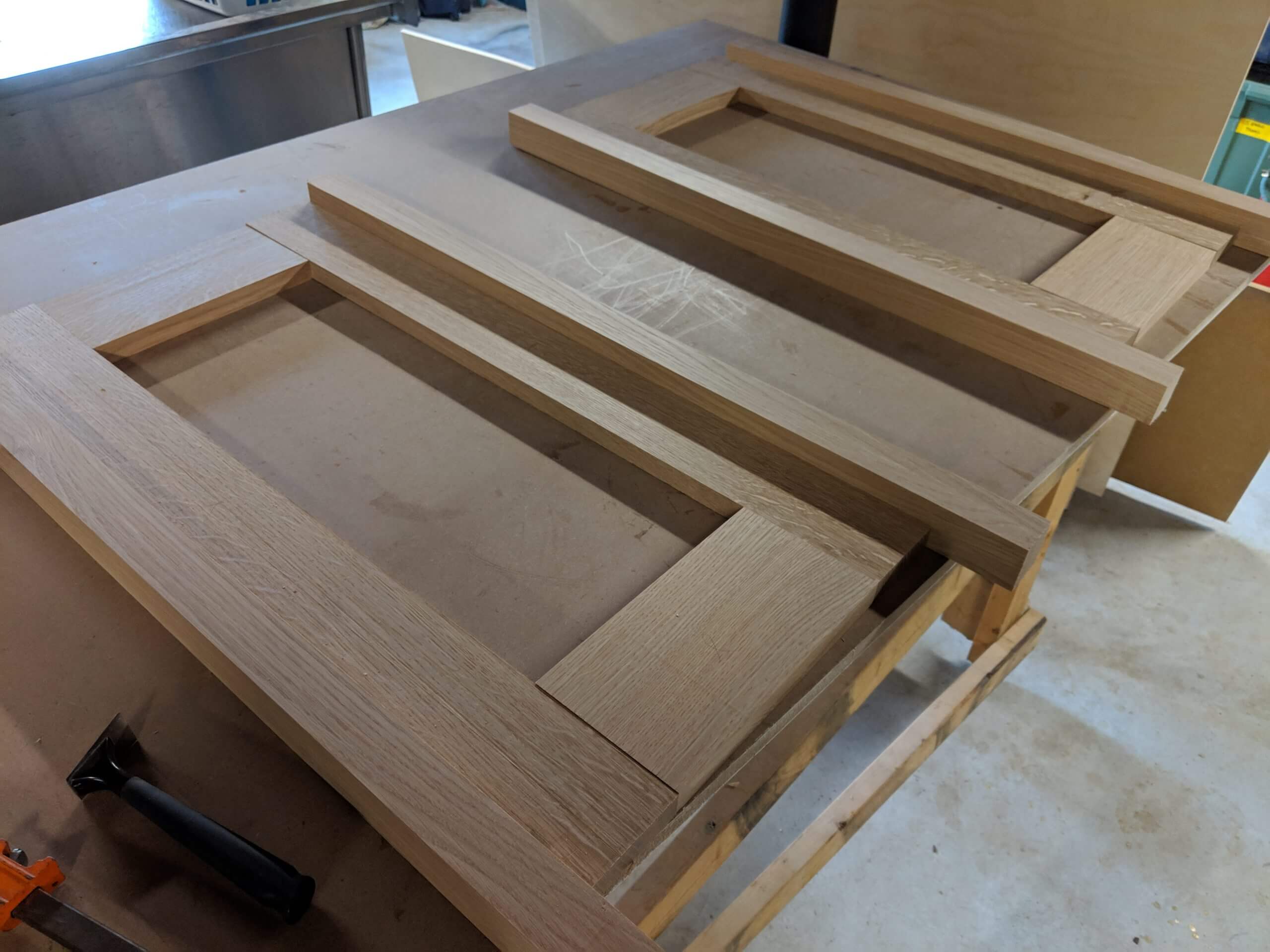
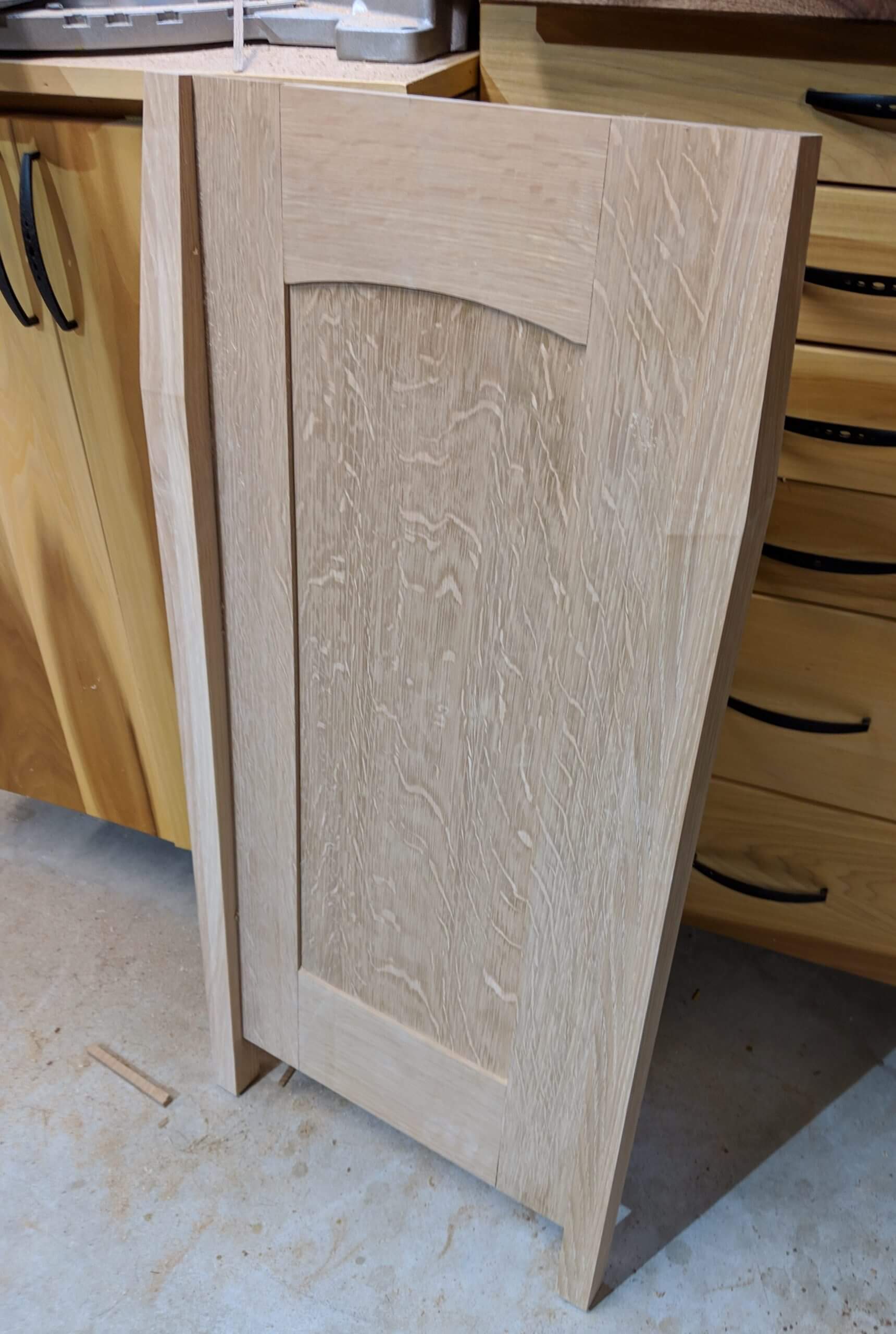
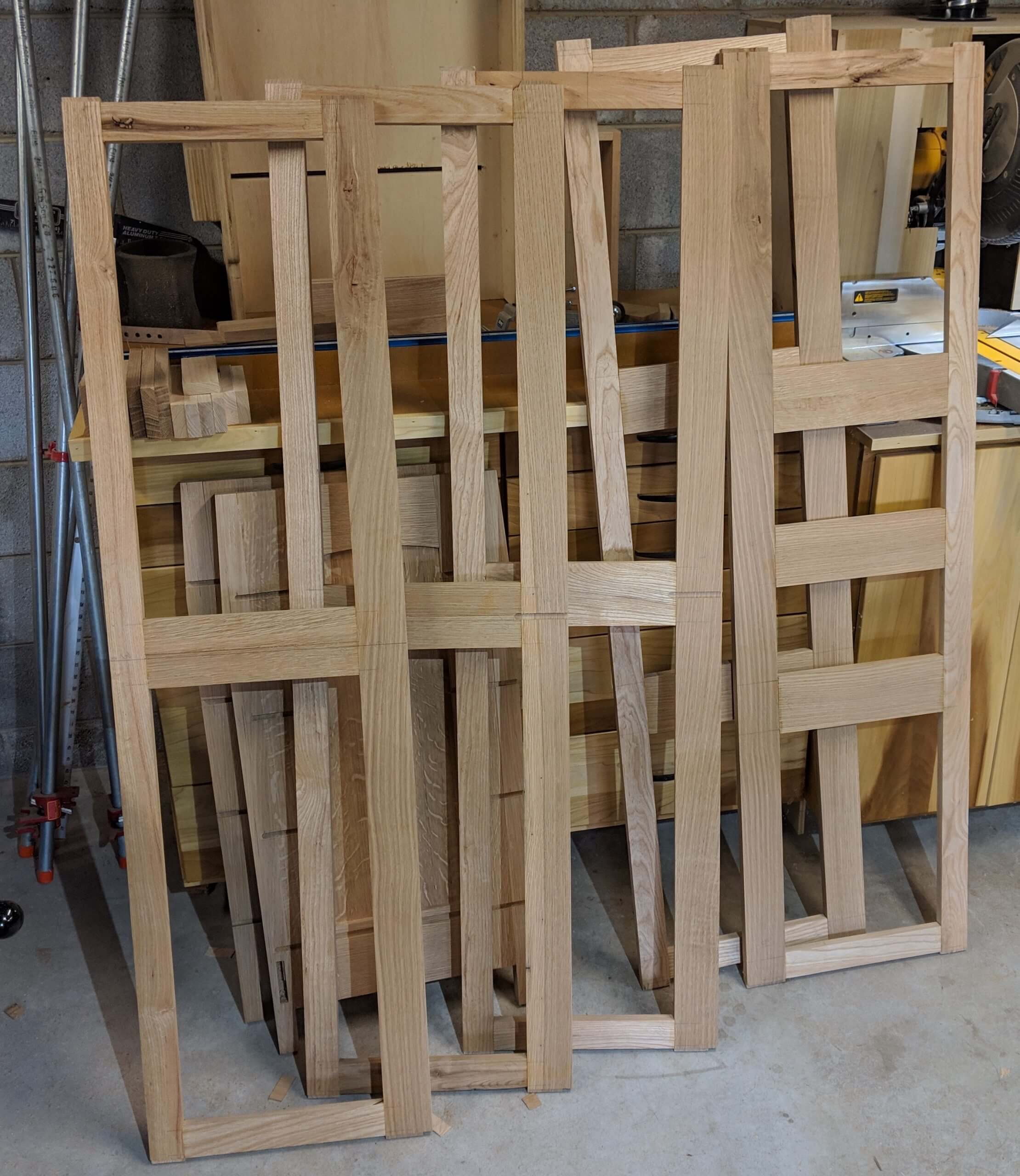
Panels
The Drawer Webs will be connected to the inside of the panel with dovetails, so you need as much thickness as possible to cut the dovetail in the stile and leg and still be able to insert the web from the rear of the carcass without binding on the center panel.
To help, I cut the stiles and rails for the panel our of the thickest stock I had. When finished off the planner it was .887″.
I tried to get the stile and rail stock out of the same board for grain similarity. The stiles are 3 3/4″ wide and 3″ shorter than the legs. They also need a 1/2″ tenon on the leg side, so mine were cut 4 1/4″ X 34″.
The top rail is 4 7/8″ wide and the bottom is 5 1/8″. These are not “magic” dimensions and you can increase or decrease them as needed. They are pulled from research on traditional Arts and Crafts furniture, though they do tend to vary. The key is they are typically wider than the stiles.
Cutting the rails is your second decision making dimension as they will establish the depth of the piece. My plan calls for 7″, but given that I reduced the width of the legs a small amount, I went with 8″ long for the rails. Each side of the rails will get a 1/2″ tenon, so add an inch to your target.
The stiles and rails get a standard panel cut, with a tenon and mortise on the rails and a long mortise on the stiles. One deviation here is moving the mortise for the panel as close to the outer edge as is reasonable. Typically you leave 1/4″ on the face side. In this case I went with 3/16″ to make the back of the frame as deep as possible for the dovetail that will be used to mount the Drawer Webs.
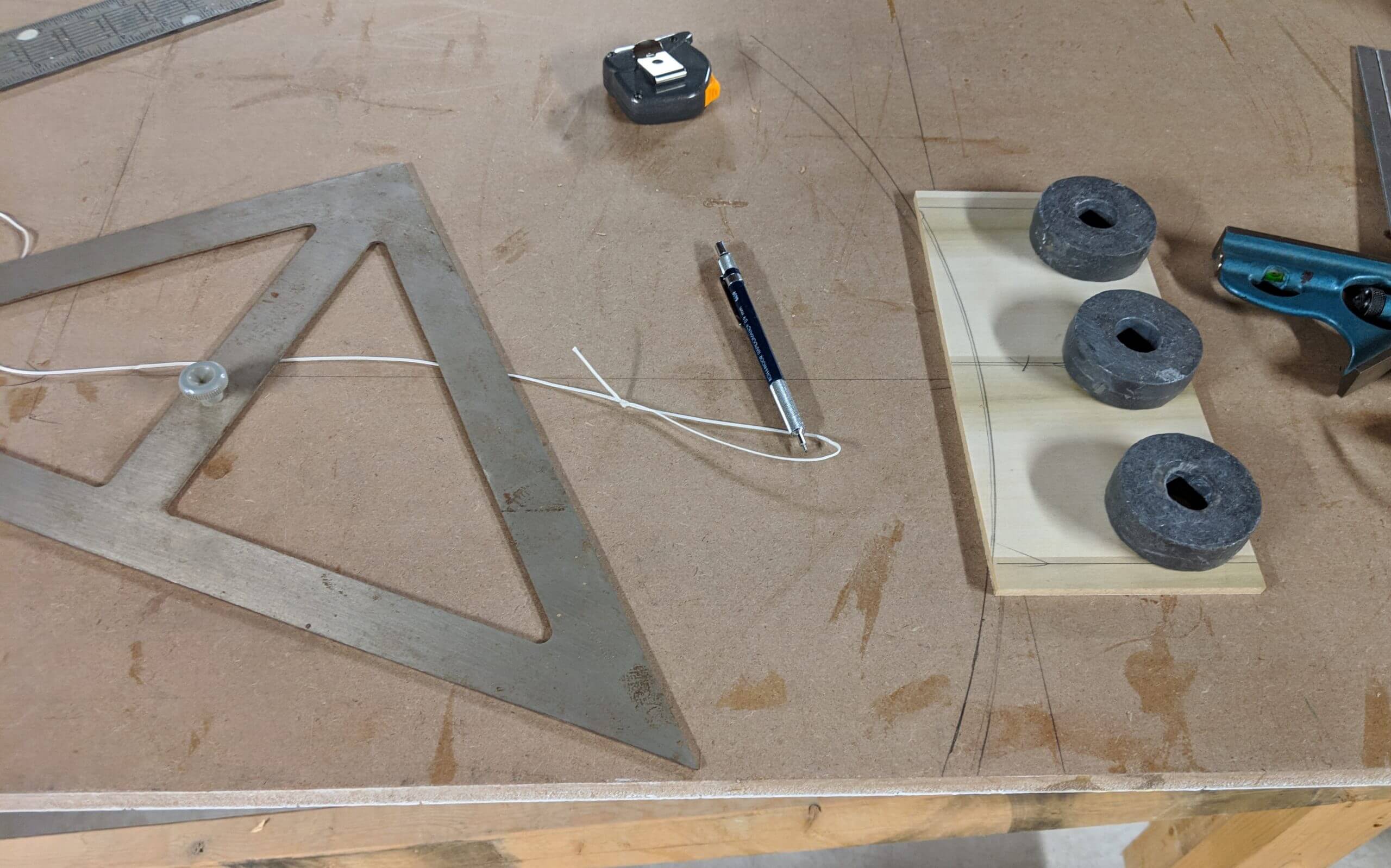
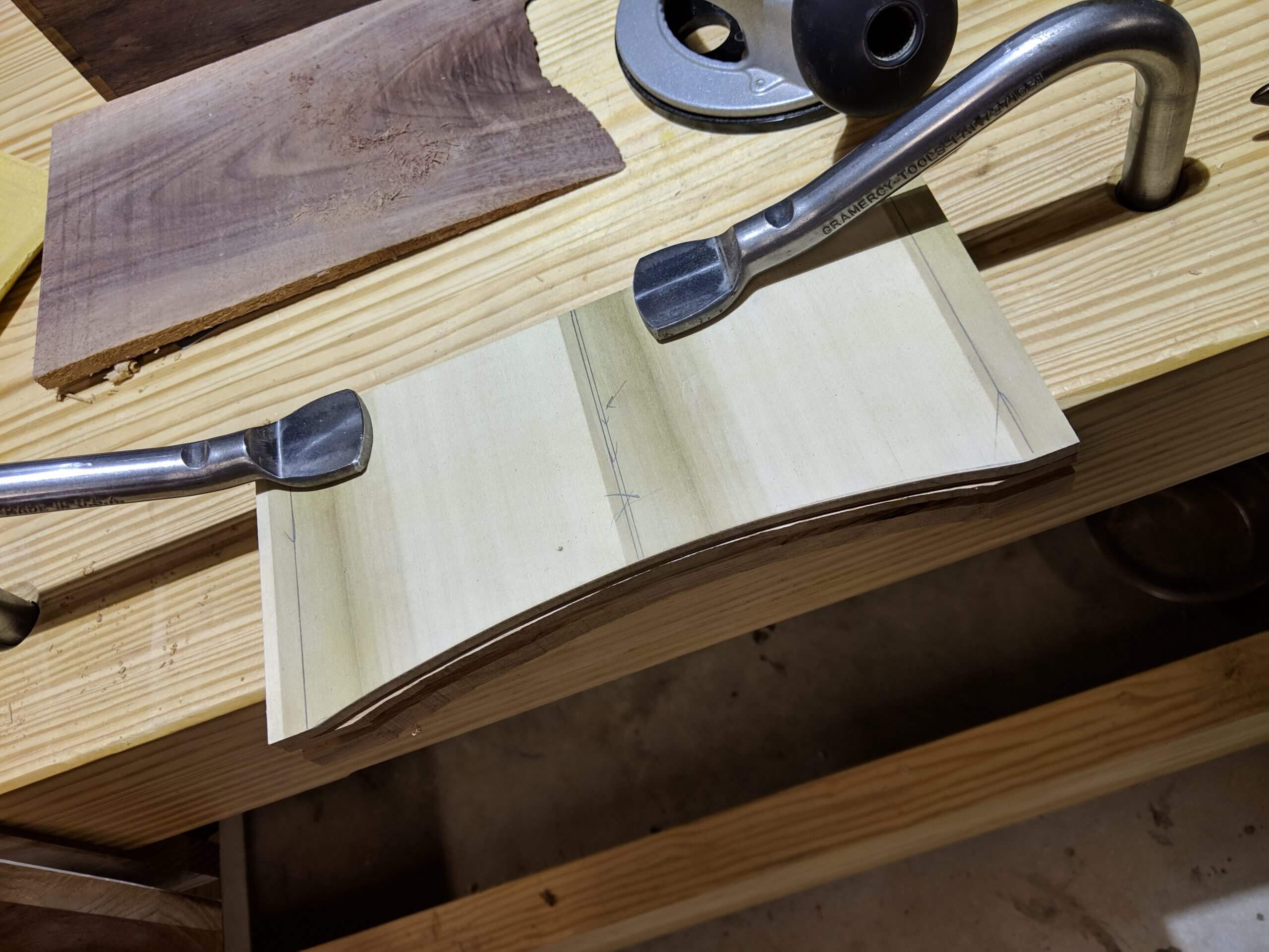
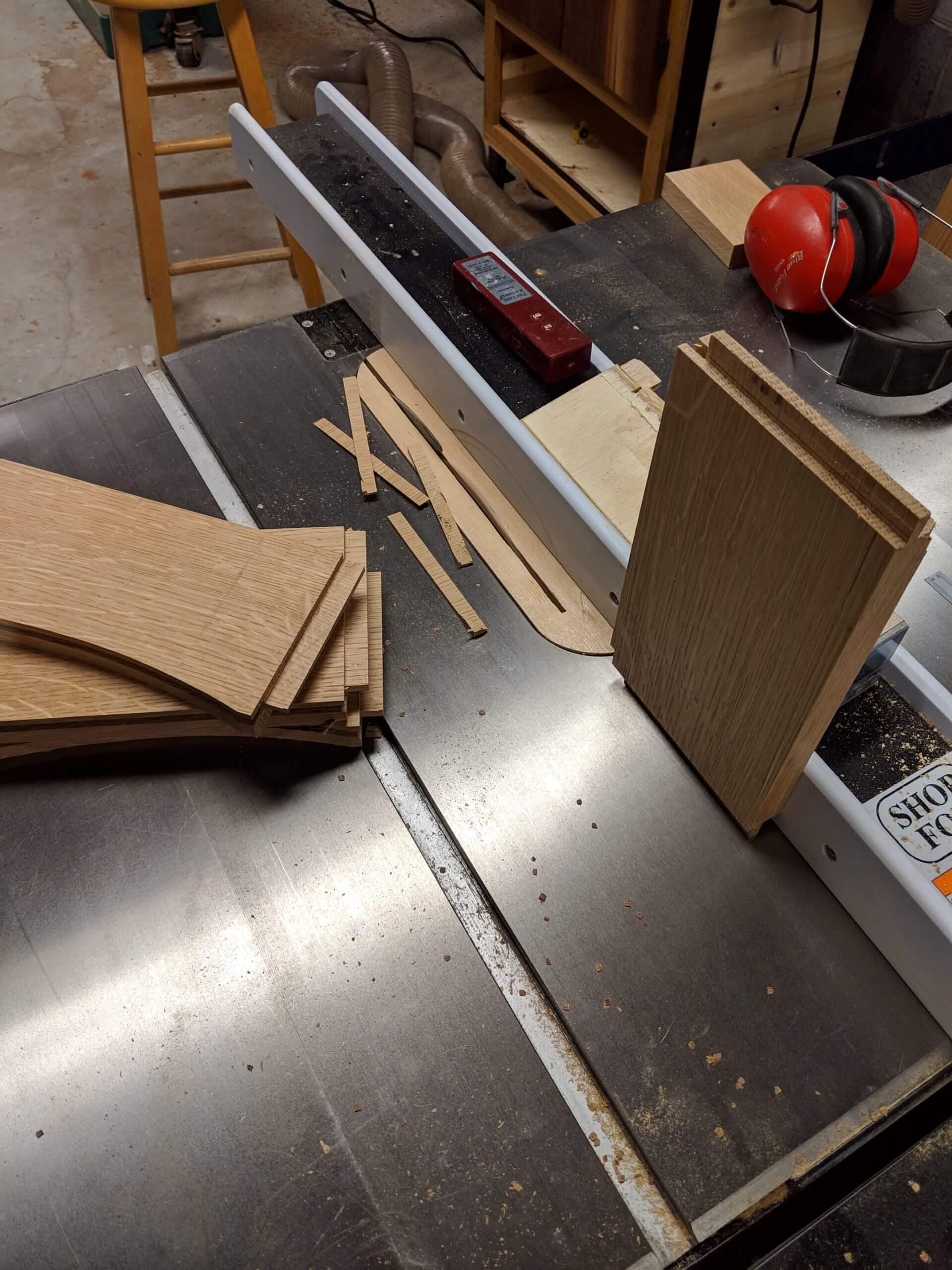
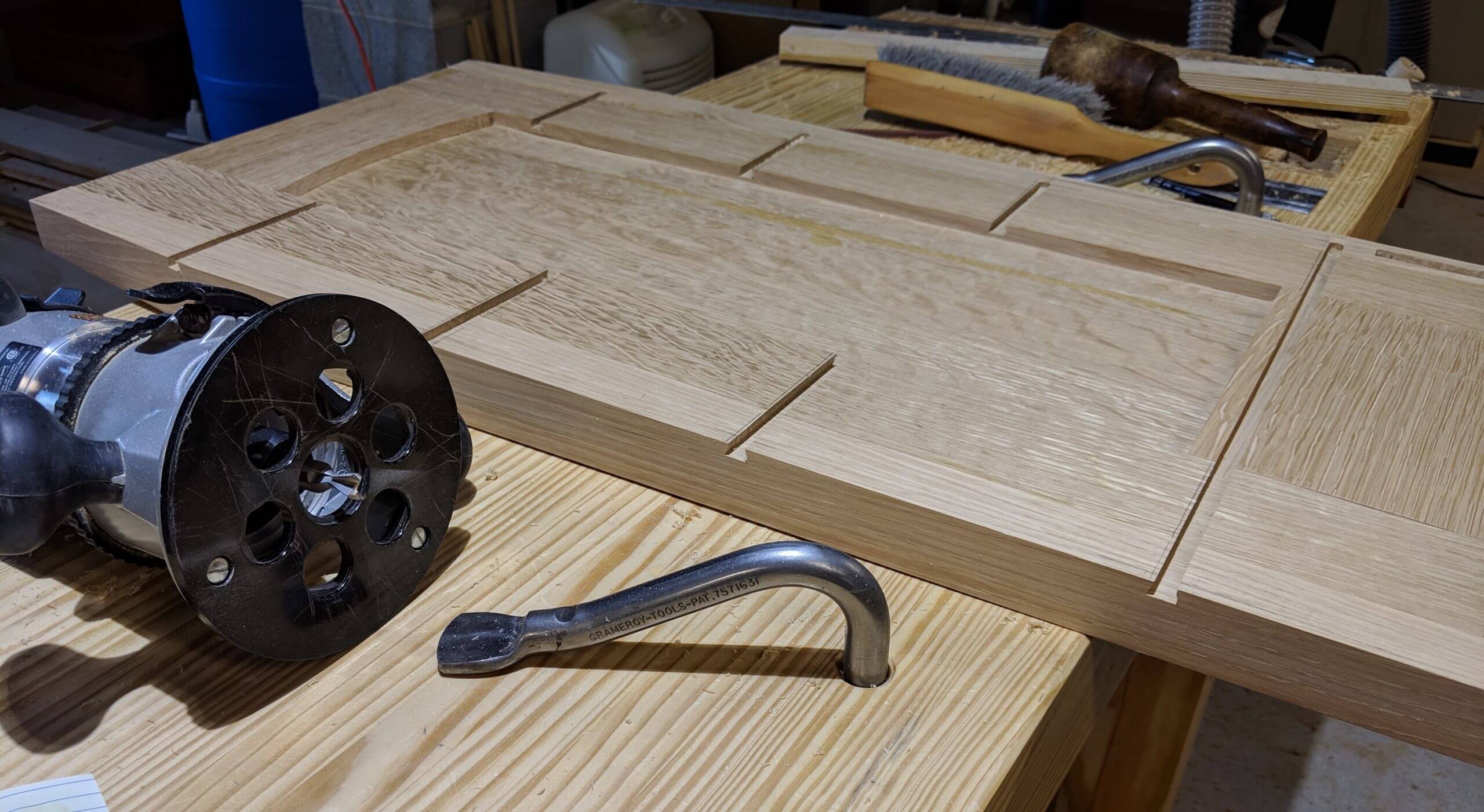
Once the stock is cut to finished size, the first milling step is to put the arch into the top rail. I made a template that is the same size as the top rail, marked a center line square to the template and marked a 9 1/2″ radius line on the template. This was cut off with the band-saw and the arch faired with sandpaper. This was used to mark the top rails that were then rough cut on the band-saw and finish cut with a flush trim bit.
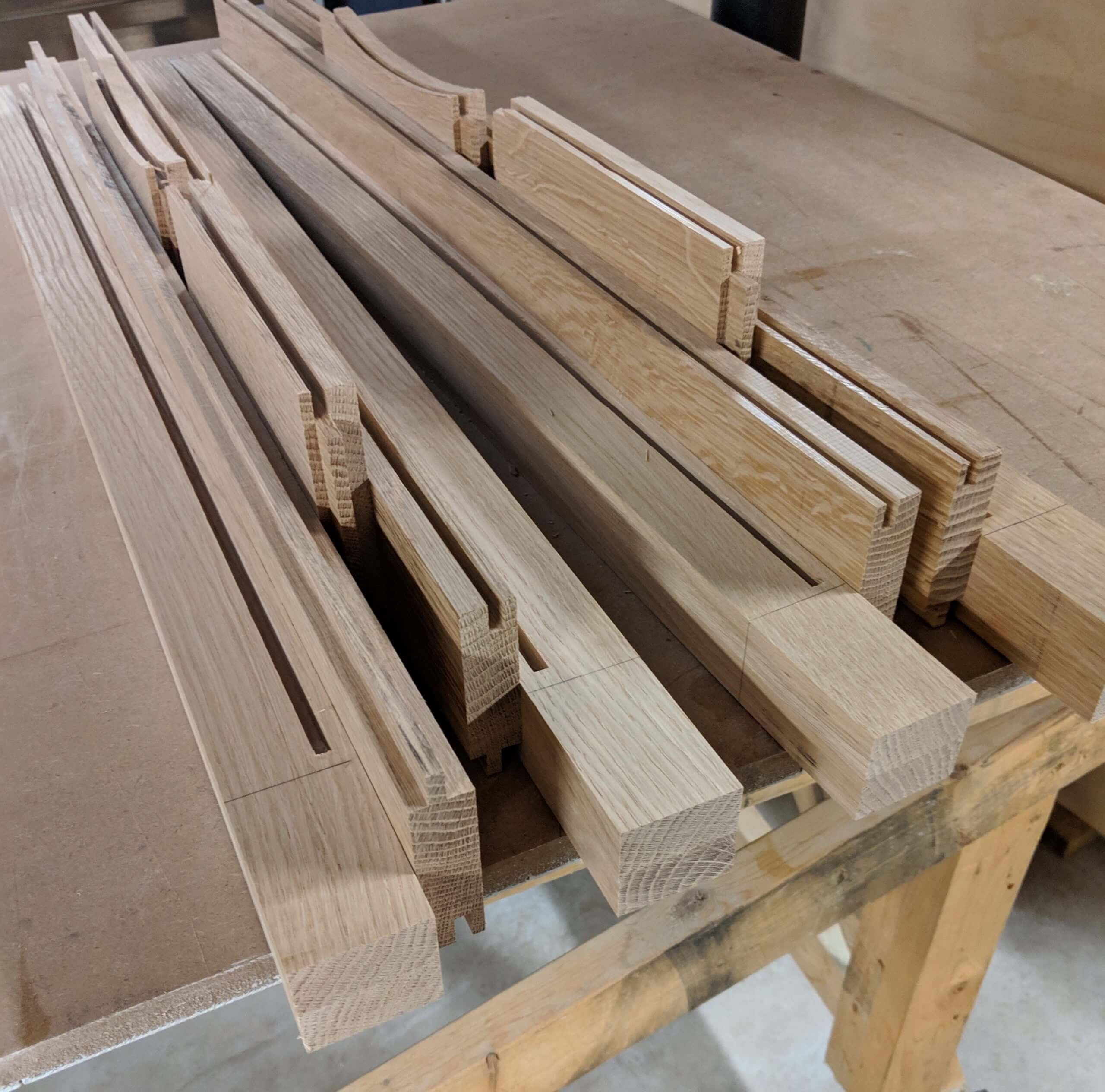
Legs get a stop slot/dado for a matching tenon on the side of the stile. The leg extends 3″ passed the stile for a foot, so make a line and stop your dado prior to hitting the line. I cut this with a 1/4″ slotting bit that is part of a drawer router set. The Stiles get a stick cut on the panel side and a cope cut on the leg side (cope cut makes a tenon and profile, stick cut makes a mortise and profile). I cut the stick cut or slot with the same slotting bit (moving the panel slot to 3/16″ from the edge). I did the cope cut on the table saw, cutting it out as if it were simply a tenon. You need to cut the lower 2″ off of the stile tenon due to the stop dado/slot on the leg.
Once cut, the parts can be dry fit so the size of the panel can be determined. Measure the opening and make it 7/8″ wider than the opening (it has a total of 1″ of slots in each direction, so 7/8″ allows for expansion).
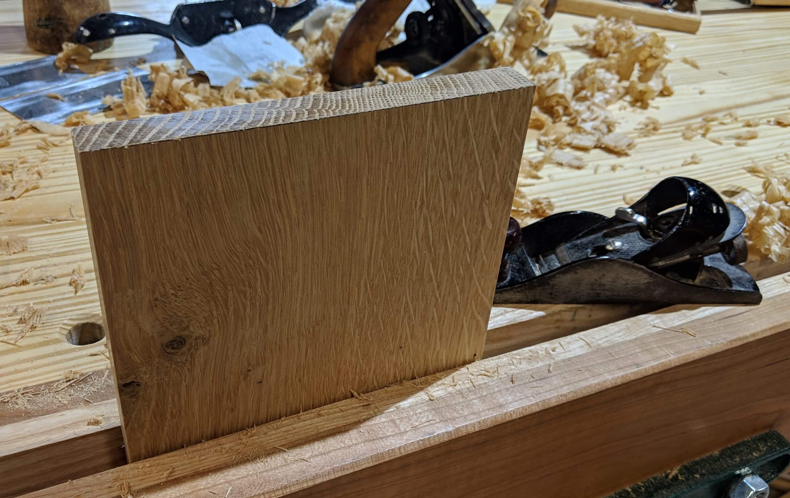
Find your best wood for the panel. I prefer to pick a 4/4 board, mill it for four edges then re-saw two 1/2″ boards out of it, then mill them down to just over your target thickness (1/4″ for my slot cutting bit) so I milled them down to 3/8″ leaving some to take off in a final planner pass once glued.
I glue up panels using a caul screwed to an assembly bench. Though my joiner is setup correctly, I account for minor variations from a perfect 90 degrees by joining one edge with the face against the fence then the other with the back against the fence. This process makes perfectly mating angels.
If there is any tendency for the panel to bow, using a sacrificial assembly bench lets you screw in another caul to hold the panel flat.
Once the panels are dry, rip them to width (I take an equal amount off of each side so the book match pattern remains and is centered) then pass it through your planner until if fits in the slot in the stiles and rails.
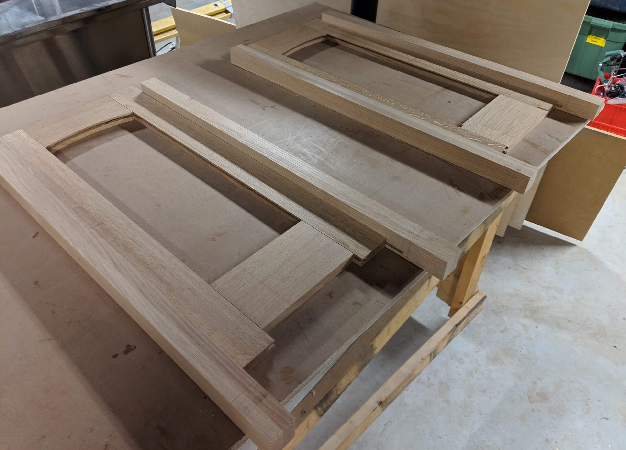
Square the end that will be the bottom using a miter saw or table saw sled then dry fit the assembly together so you can mark the arch. I place the top rail in place and mark the arc the move it 1/4 up and mark the line to be cut. This can be rough cut on the band-saw.
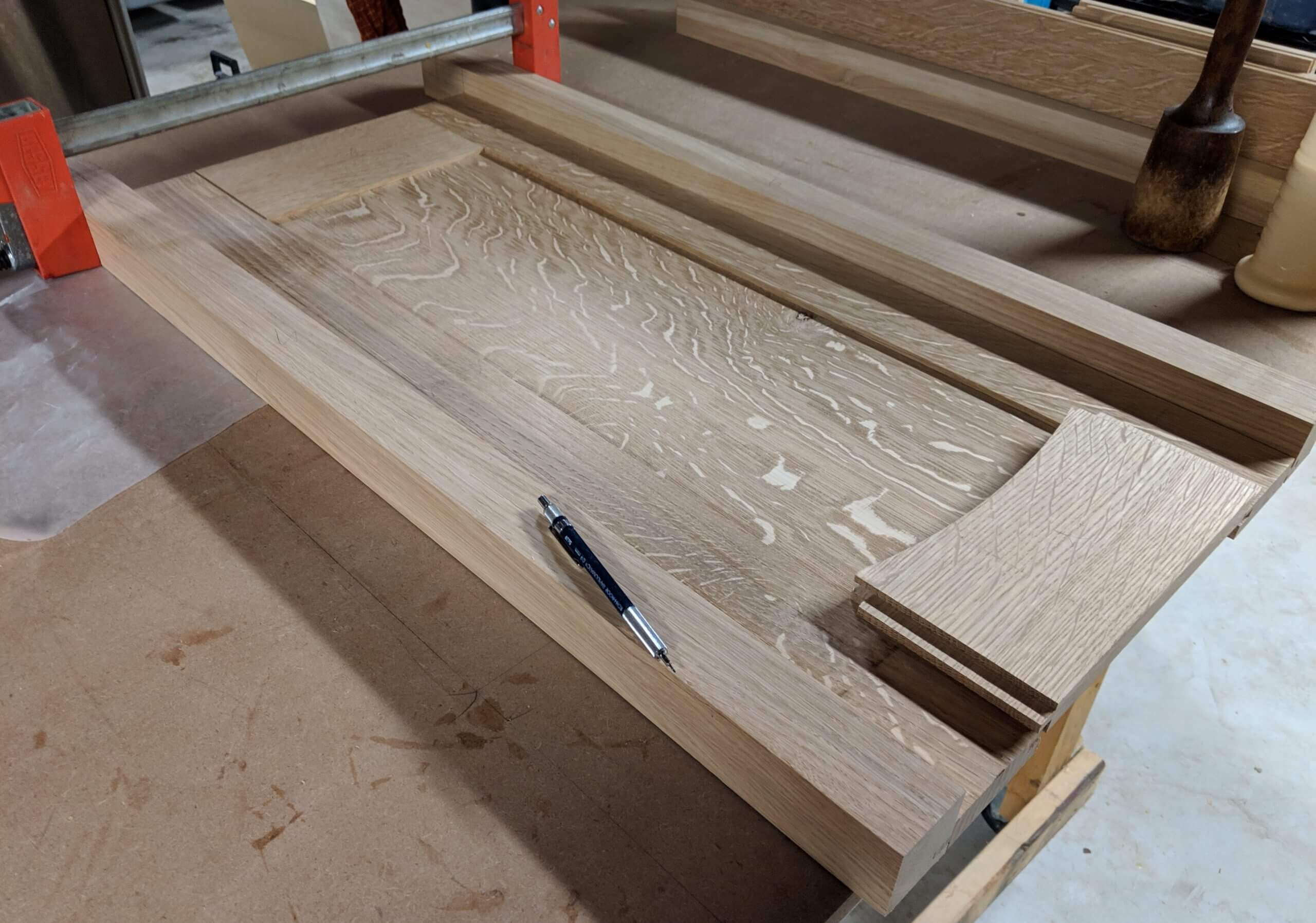
Once cut to size and confirmed with a dry fit of the entire panel, the center panel can be removed and gone over with a card scrapper and sandpaper. After the panel is assembled it is hard to work the center. The same goes for the inside edges of the stiles and rails.
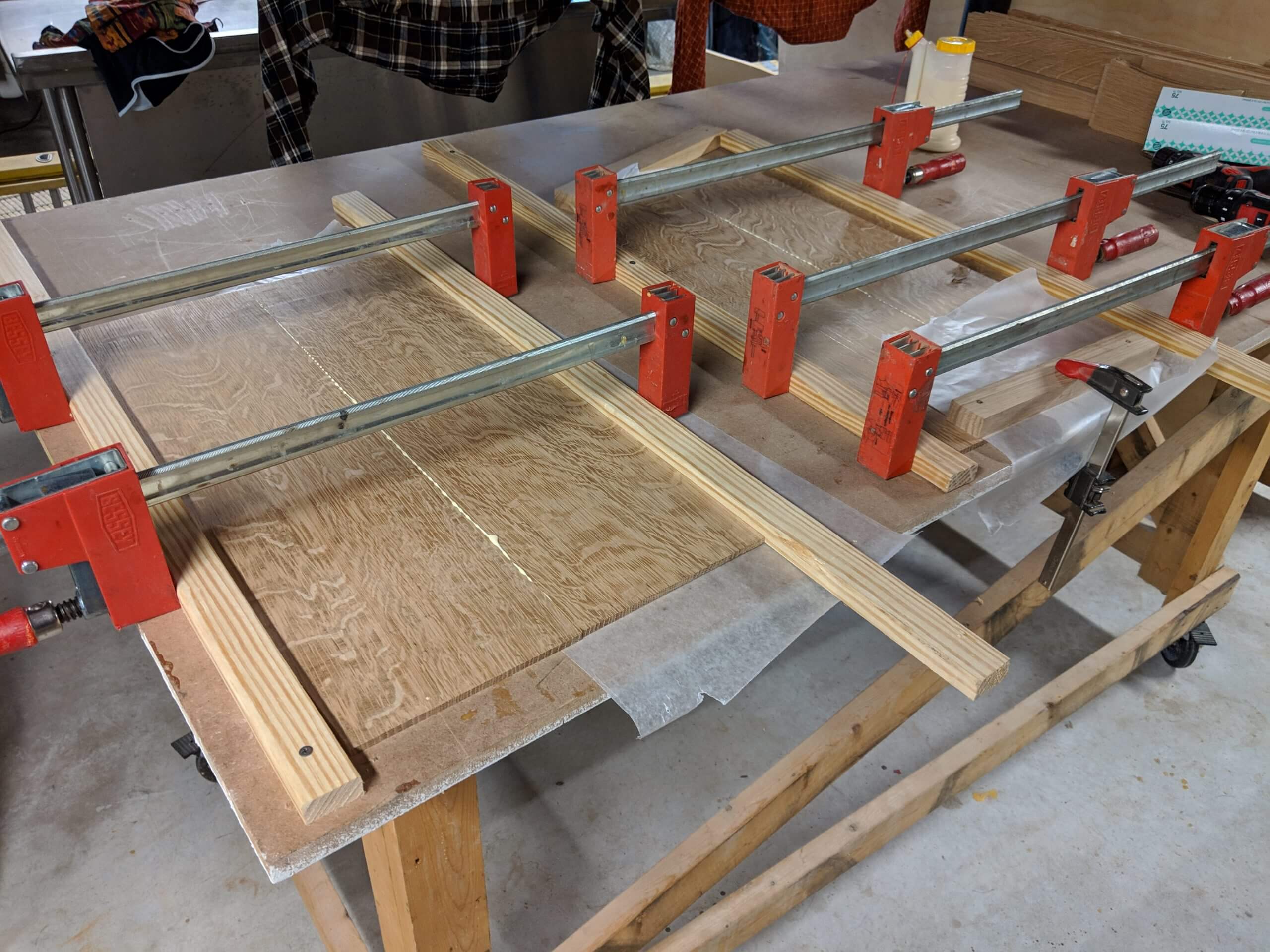
Once satisfied with the center, glue the entire panel together.
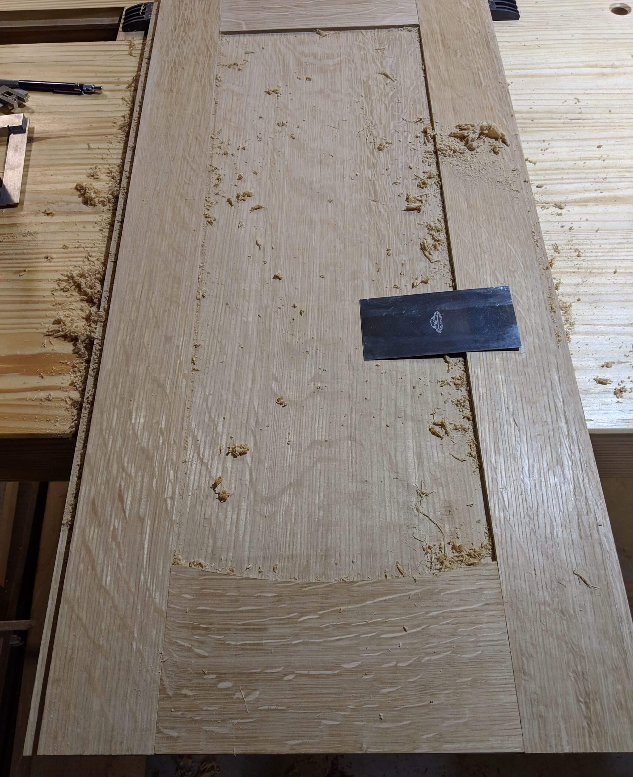
When the panel comes out of the glue-up, use a plane to adjust any lip left in the stile to rail joint (inside and out) then use a sharp card scrapper to flatten the entire surface, looking for tool marks from the planner and tear out that needs to be removed. After scrapping, sand with 220 grit paper. Take your time. There is nothing more frustrating then putting a piece together and finding a spot your missed!
Prior to gluing up the panel and leg assembly, the leg needs a mortise for the arched center stretcher. The leg extends 3″ below the stretcher and the stretcher is drawn as 4″. Though the cross stretcher has not been made, you can assume it will have a 1/2″ tenon and a 1/2″ shoulder on each end and be milled to 3/4″ so it will have a 1/8″ shoulder on each side.
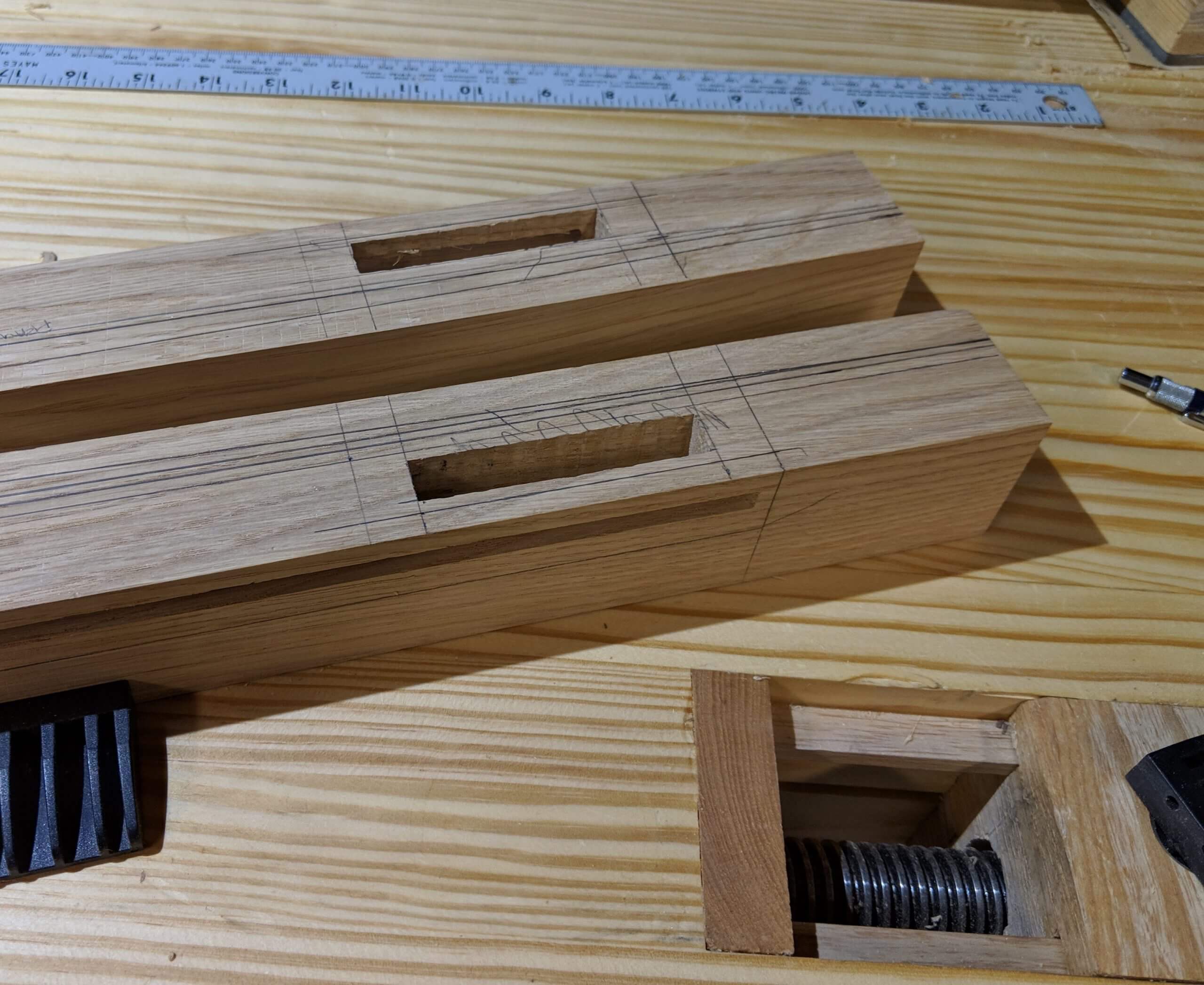
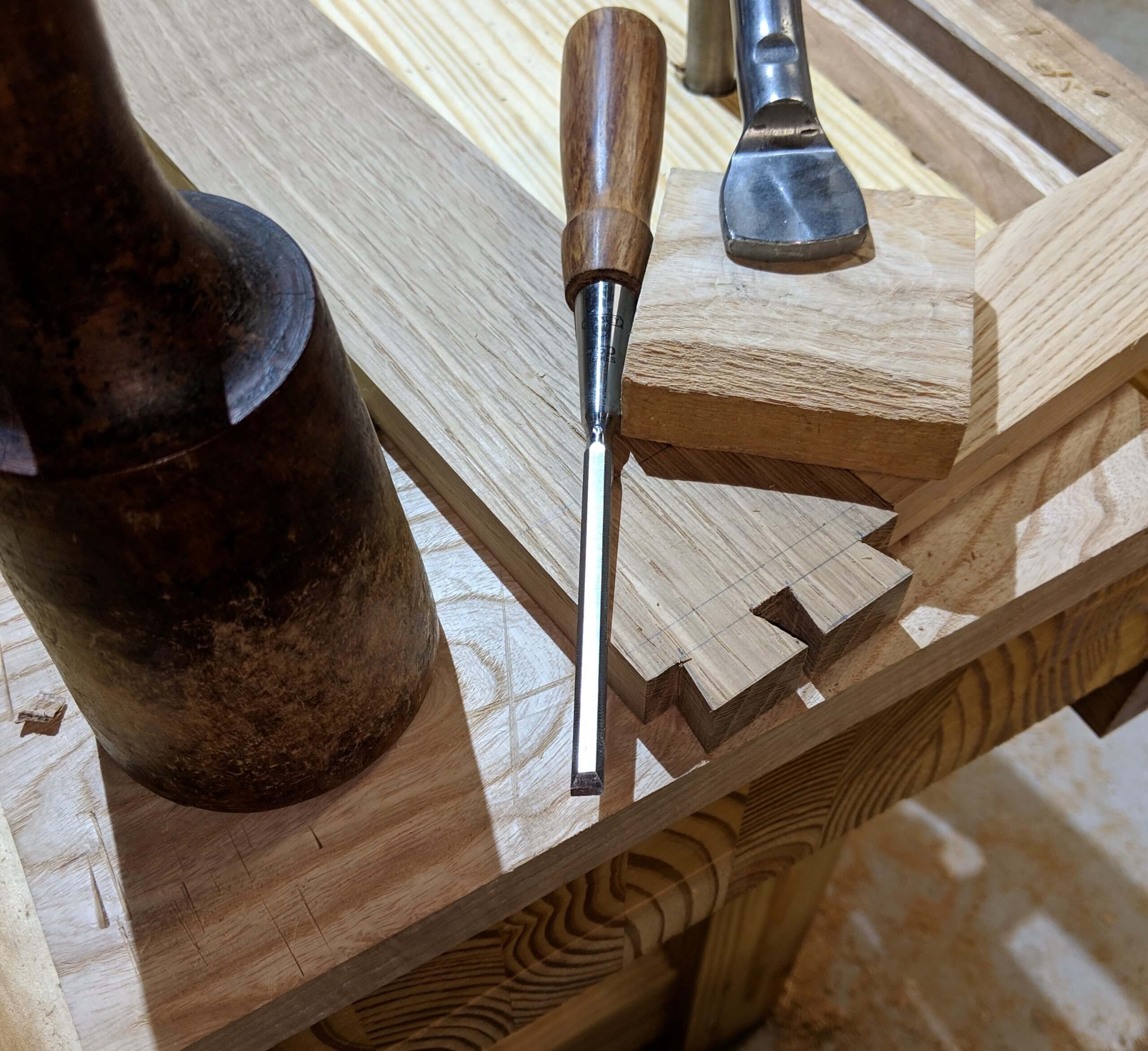
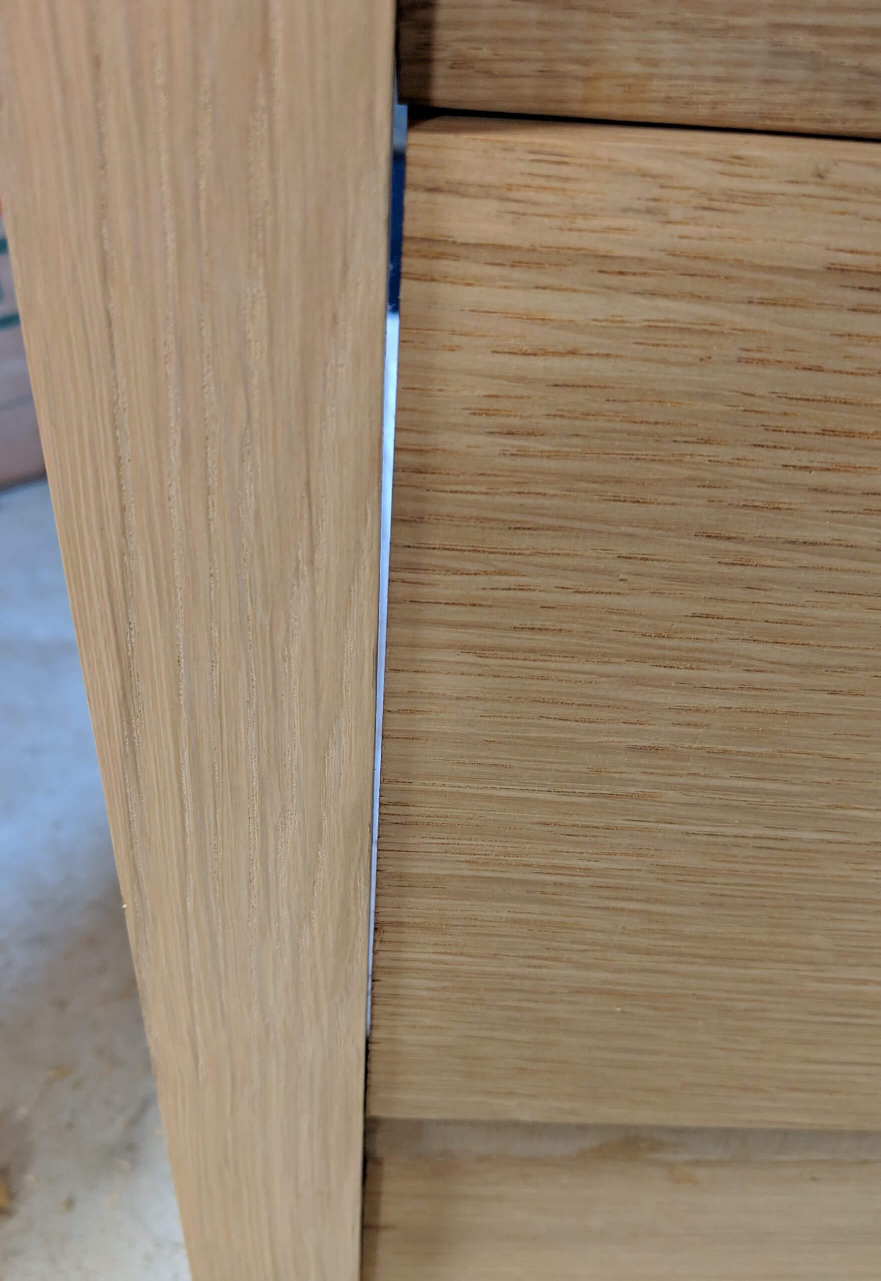
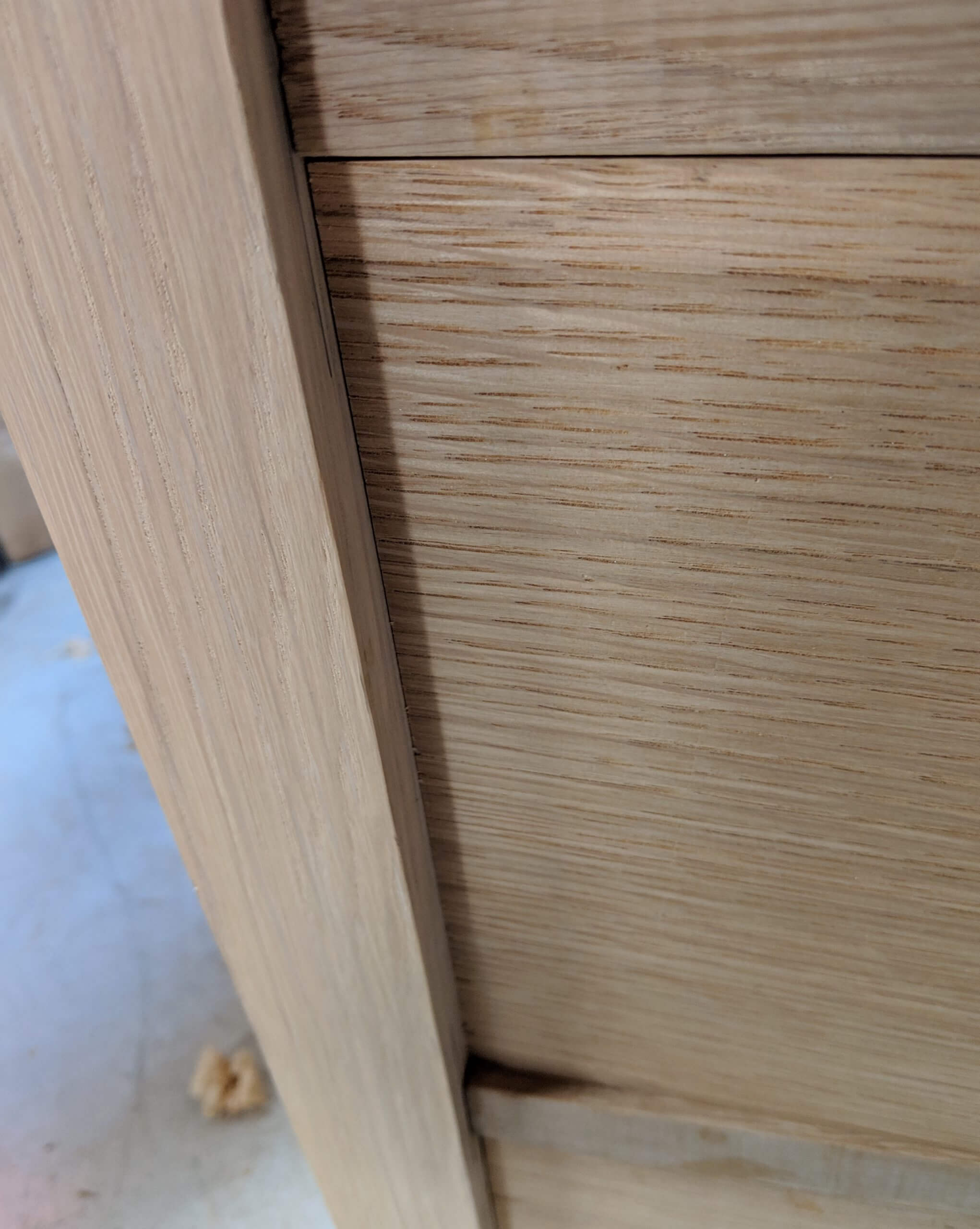
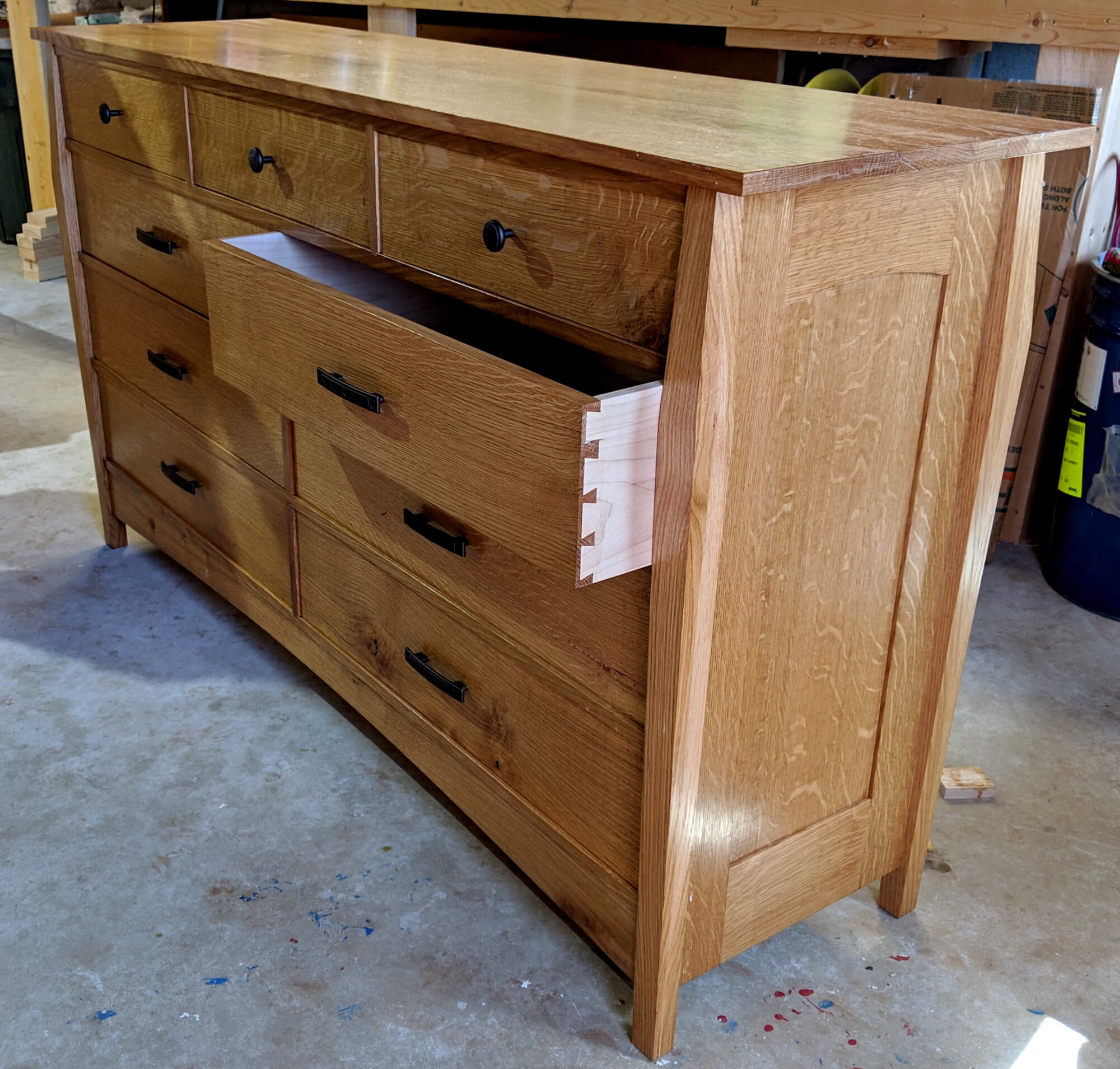
One key visual element to the dresser are the stepped reveals of the drawer dividers. The dividers are set 1/8″ back from the leg at the narrowest point and the drawer faces and lower stretcher are set back an additional 1/8″.
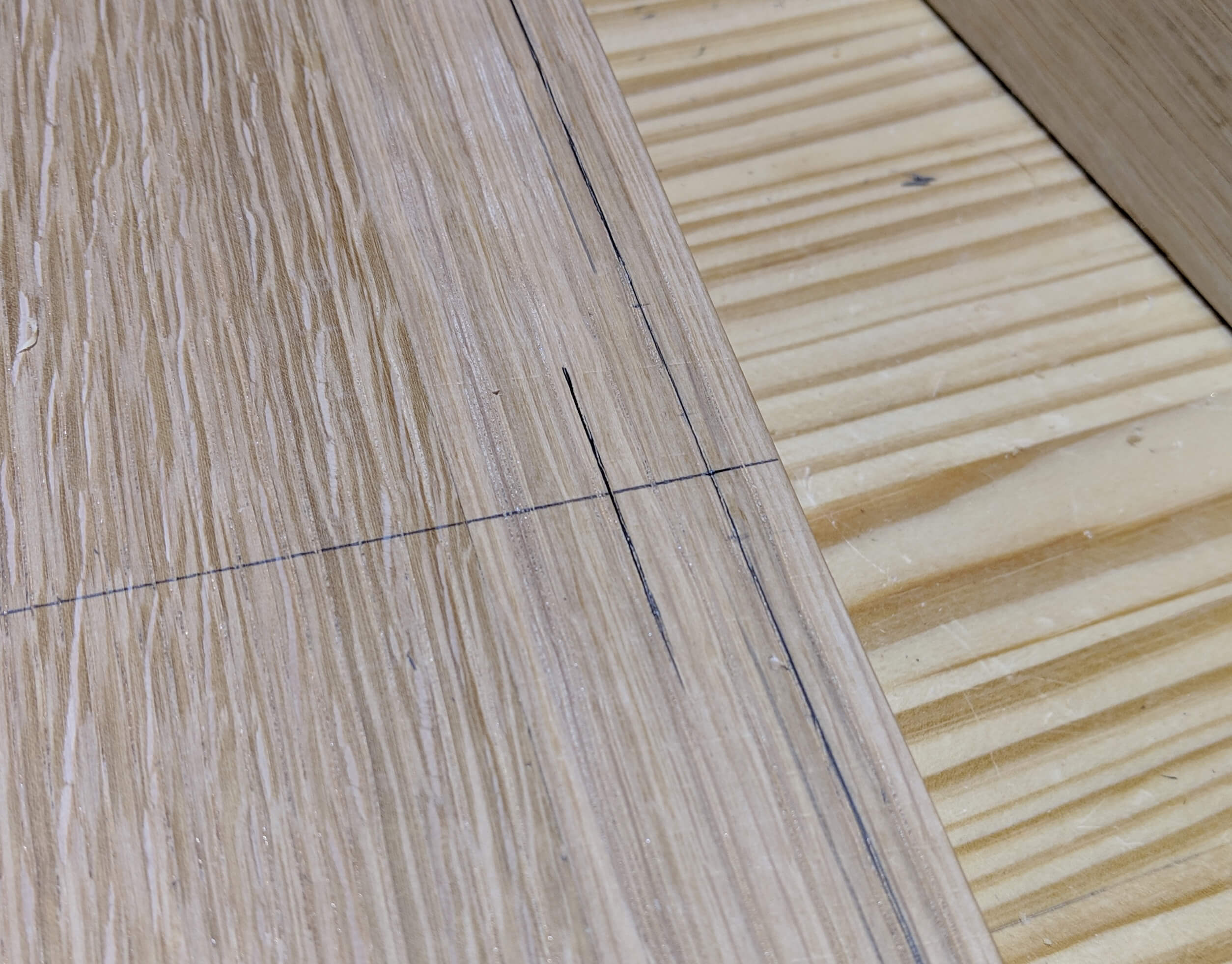
To lay this out first mark the taper on the leg. I use a double taper from a point 29″ up from the bottom. I mark a point 1/2″ in from the bottom and the top and connect it to the edge at the 29″ point. This is the red line in the drawing.
Next come in 5/8″ from the front of the leg and make a line parallel to the leg sides (this is 1/8″ in from the extent of the taper at the top and bottom). This is the Blue line and will be the Drawer Divider reveal point.
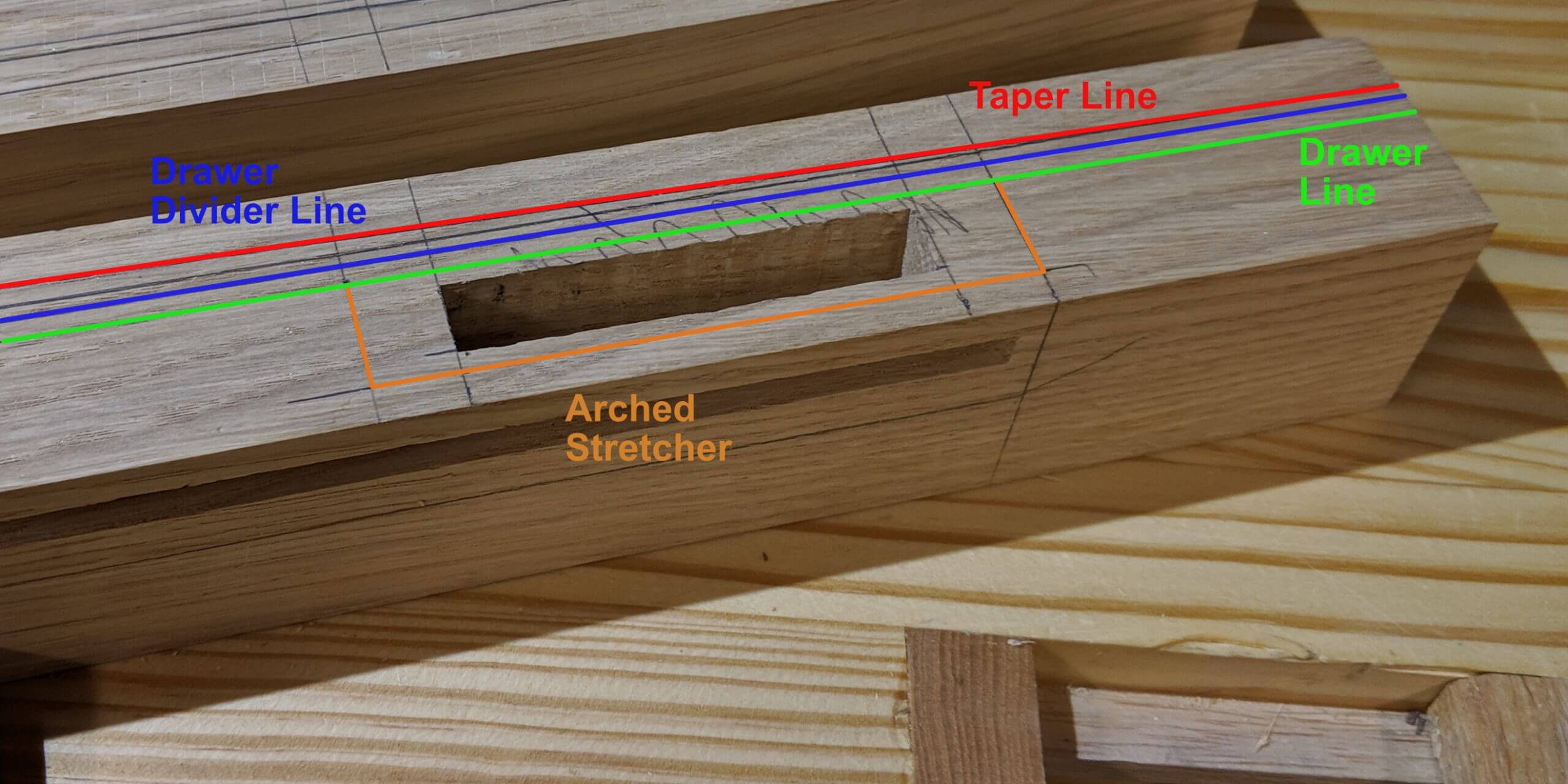
Come in 1/8″ from the Drawer Divider line and make another line for the drawer faces (Green line in the drawing).
The arched stretcher will have a face that falls on this line, so you can layout the location for the stretcher and mark the mortise (Orange Line).
Once the mortises are cut you can cut the taper on the legs (remember you are cutting two sides, the face that is towards the front/back and the outer face). I would be lying if I said I did not double and triple check to make certain I was not cutting the wrong face. One easy way to keep it straight is to do a dry assembly and mark the waste areas with a marker.
There are numerous ways to cut a taper. Custom jigs, work holders and the like. I simply cut to the waste side of the line on the band-saw, roll the piece and put the cut off back under it to support it and make the second cut. From there the flat part gets two passes on the joiner running down hill. Cutting to the waste side lets you take off the line on the joiner and results in a smooth finish. I do count the joiner passes and if one needs a third they all get a third pass.
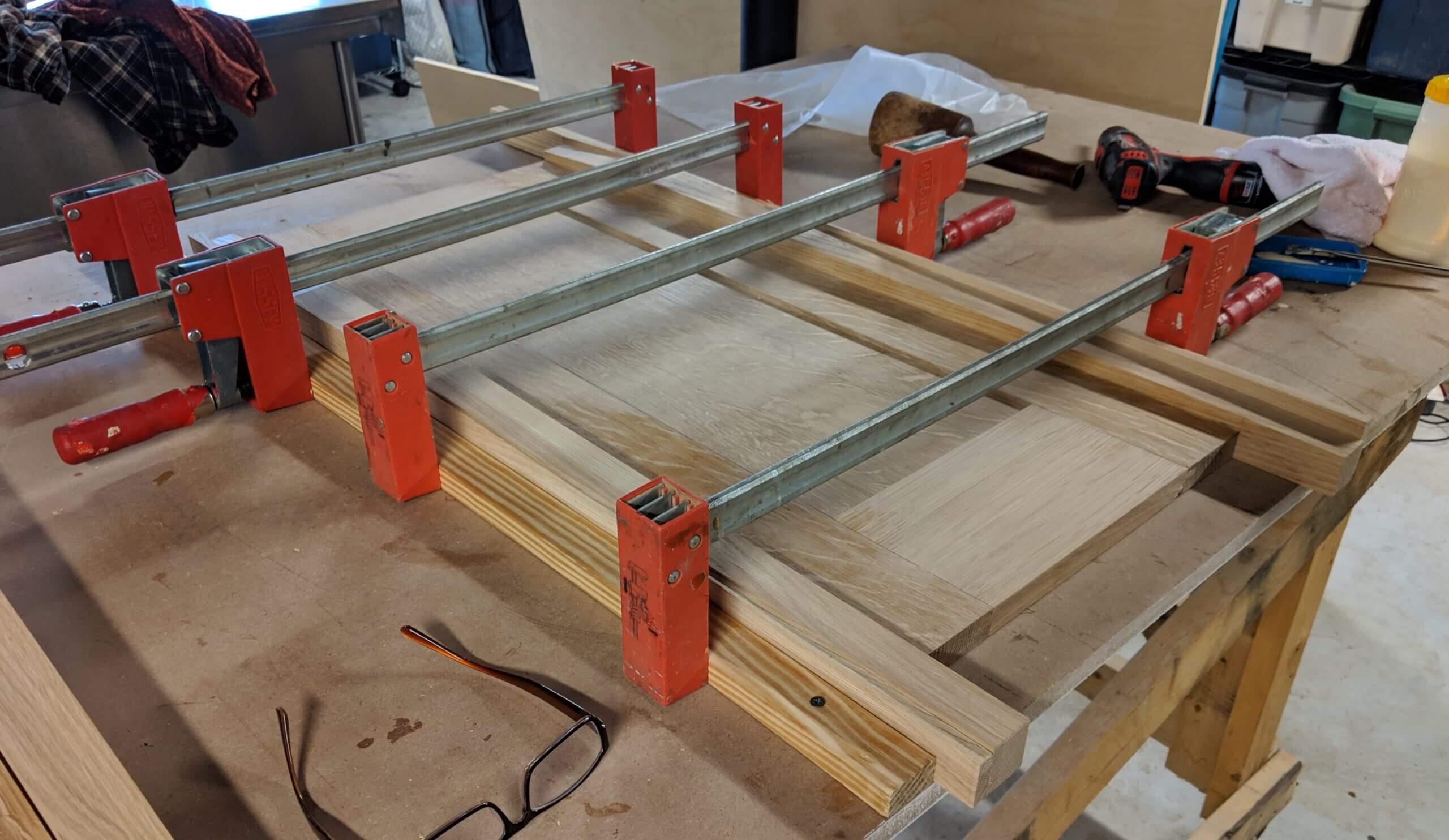
Once the legs are tapered and mortised, you can glue them to the waiting panel. Use the cut-offs from tapering the legs as cauls for clamping.
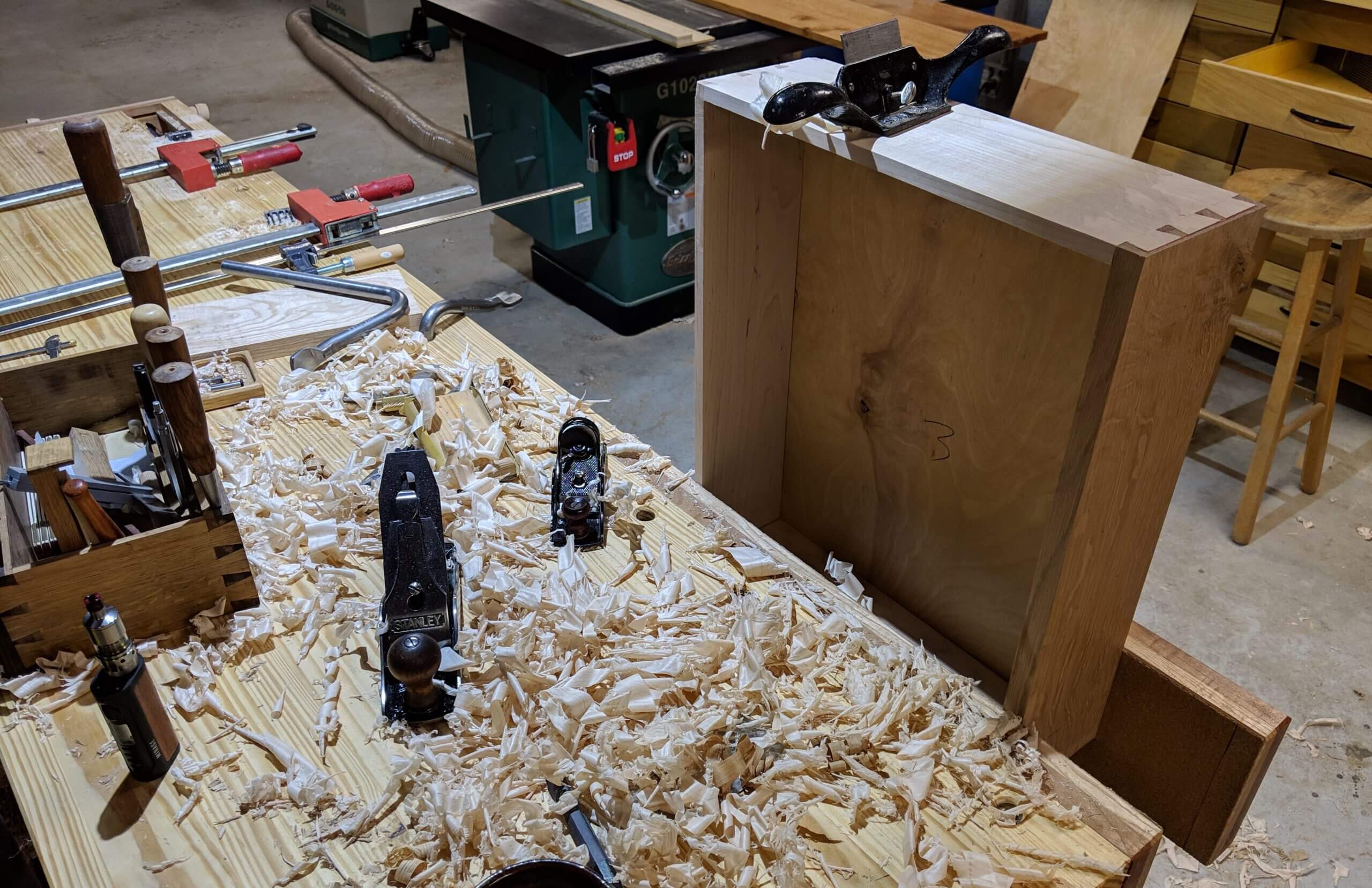
When the now complete panel/leg assembly comes out of the clamps, go over the legs with a card scrapper and sandpaper, removing any tool marks left from the joiner. As in many other steps, take your time scrap it smooth. You or whomever you are making this for will have it for decades, so an extra 20 minutes or card work is worth it. On one leg I had to break out a smoothing plane and a cabinet scraper to get the finish just right.
The next step is to cut the dovetails in the back of the stiles and legs to accept the Drawer Runners, but their location can’t be determined yet as the stock has not been milled. Though this is not an issue for the middle and upper ones, but the lower has to fit with the arched stretcher so prior to cutting the dovetails the stock will be milled to determine the thickness. Put another way, you can’t mark for drawer layout until you know how thick your Drawer Webs will be as it will impact the hight of the drawers and their layout.
Drawer Webs and Assembly
Drawer Supports run on the front of the carcass, they connect to the sides and to Drawer Runners that in this case run to rear Drawer Supports. The Drawer Runners are typically not glued, but ride on loose tenons as the side panels expand and contract. When assembled with front and rear Drawer Supports the assembly is called a Drawer Web. A Drawer Web can be fully glued if the sides of the carcass are constructed as a floating panel. As such, these will be fully glued as they will be a principal form of strength in the finished dresser.
This dresser also features vertical Drawer Dividers that connect the horizontal Drawer Dividers. One is included in the lower three tiers of draws and two in the top tier. The Drawer Webs will need to feature additional Drawer Runners at these points.
Only the front Drawer Support will be visible in the finished project, so only it needs to be made from the same wood as the rest of the dresser. You can use a less expensive wood for the Drawer Runners, rear drawer Supports, center Drawer Runners and side guides.
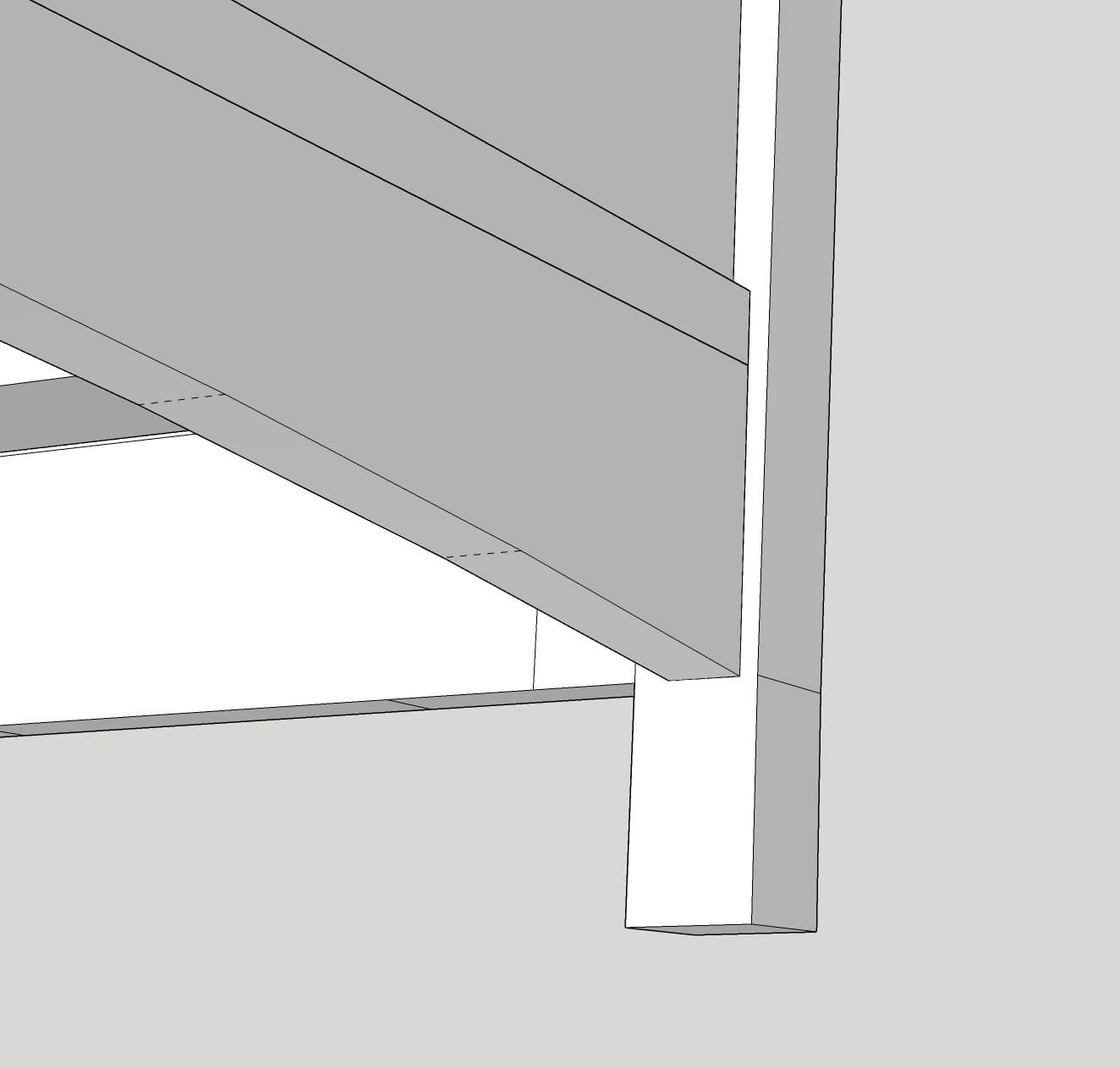
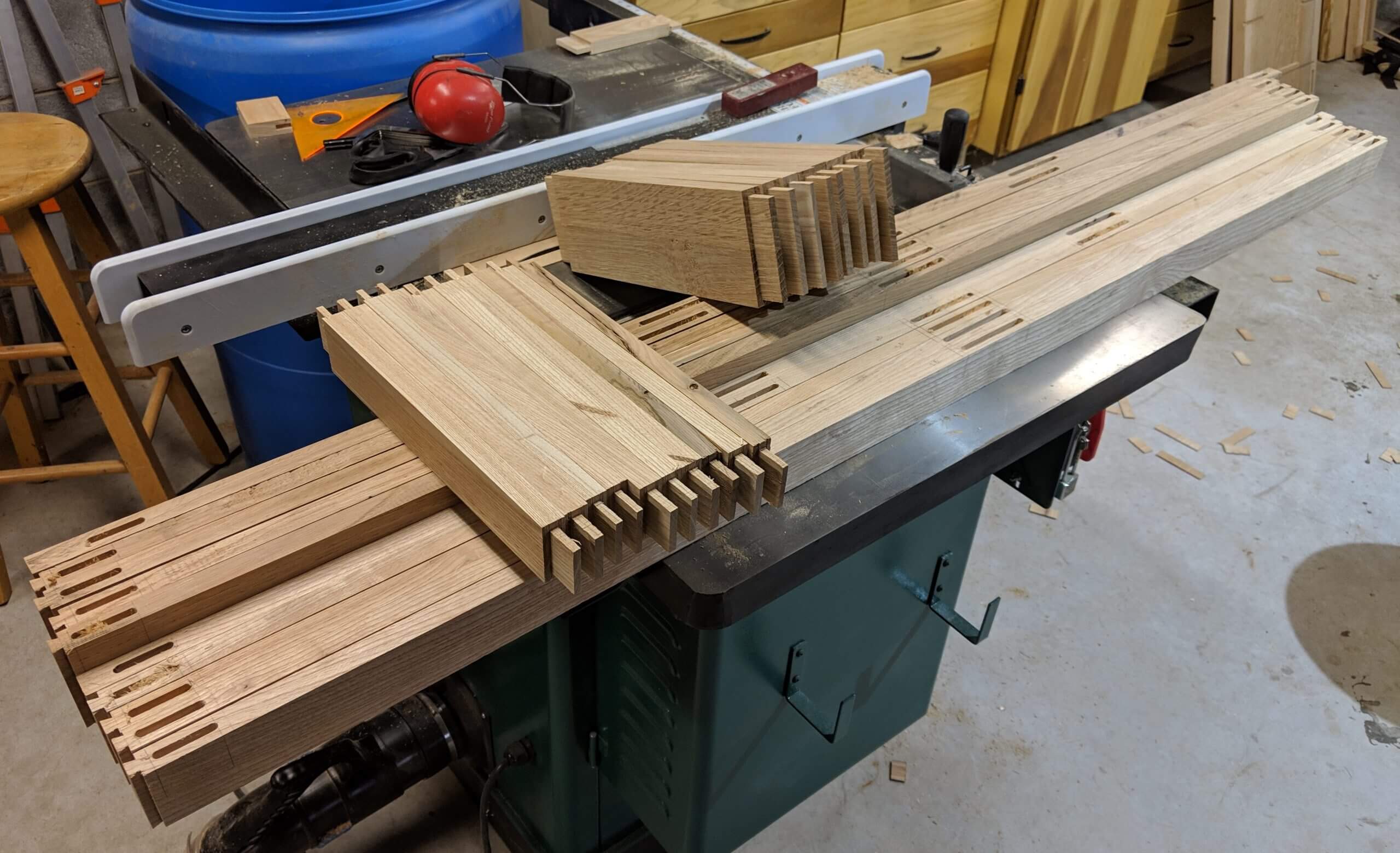
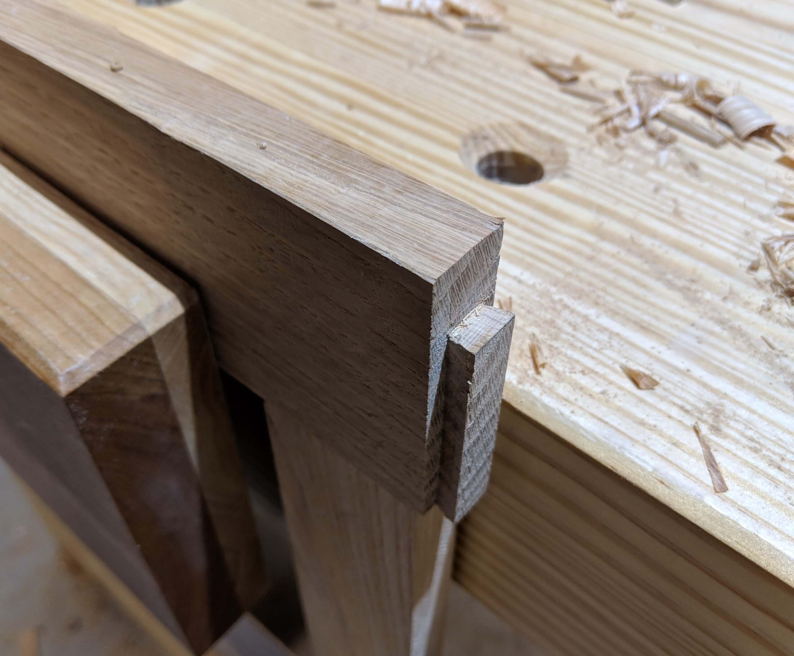
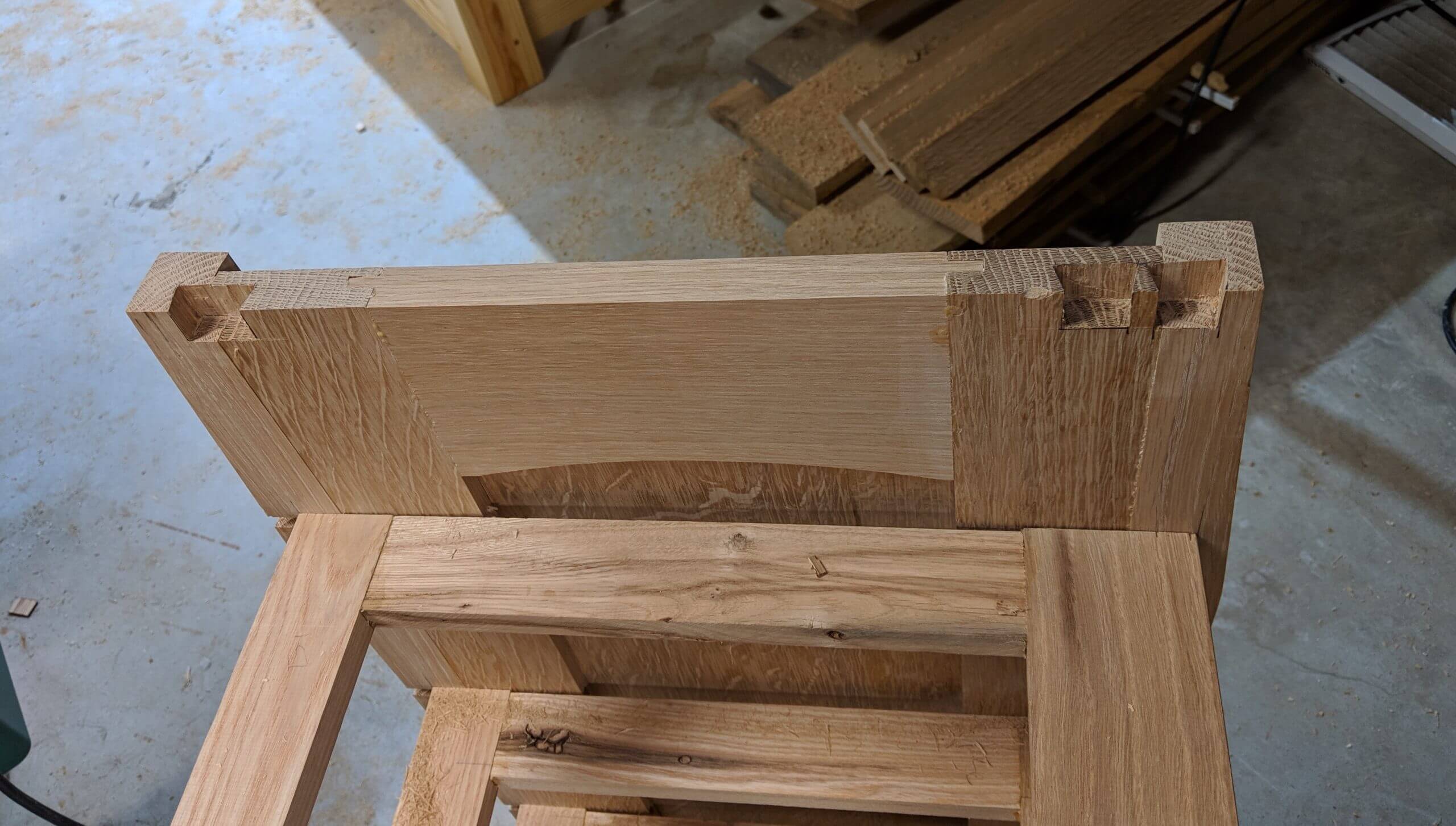
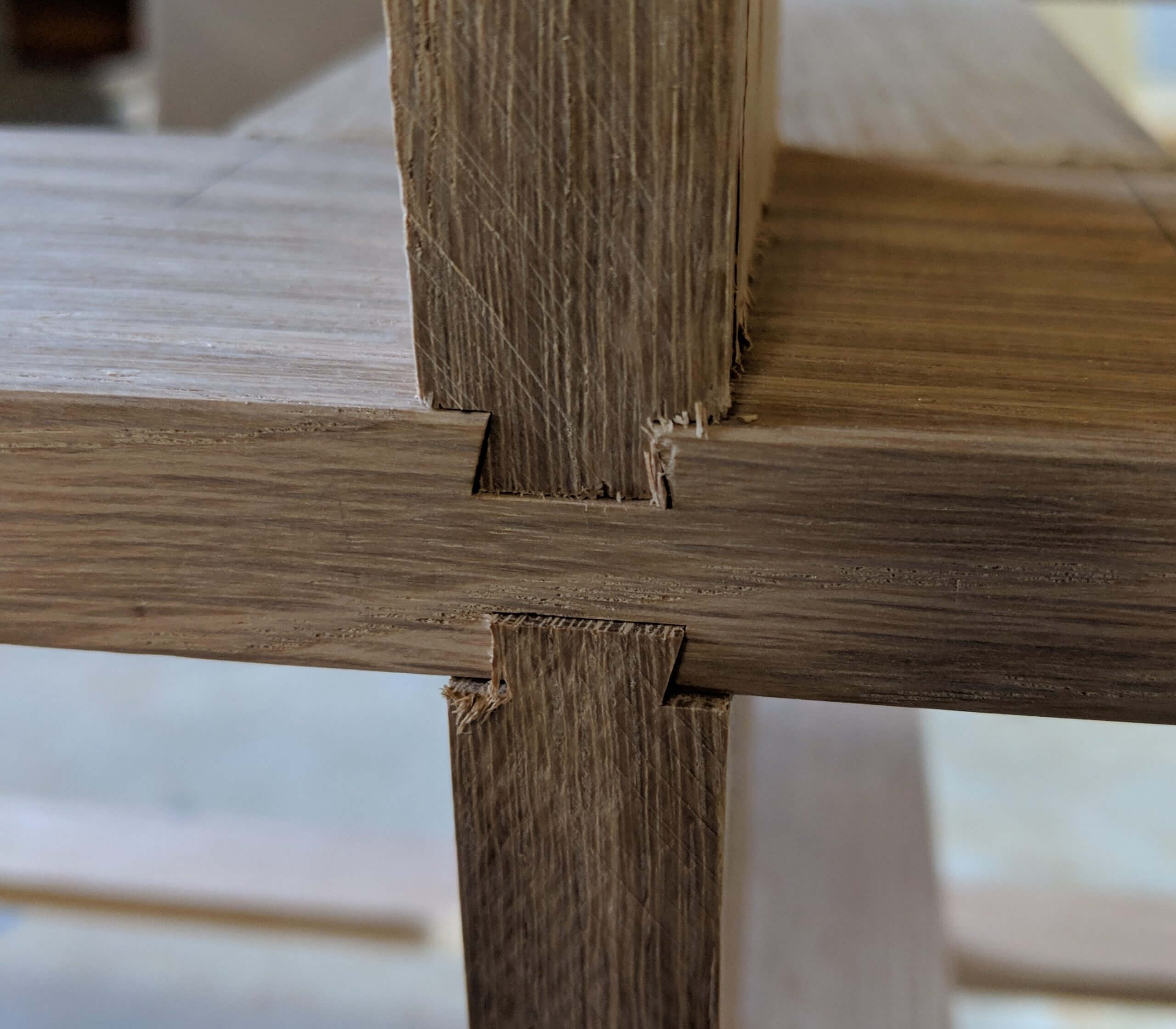
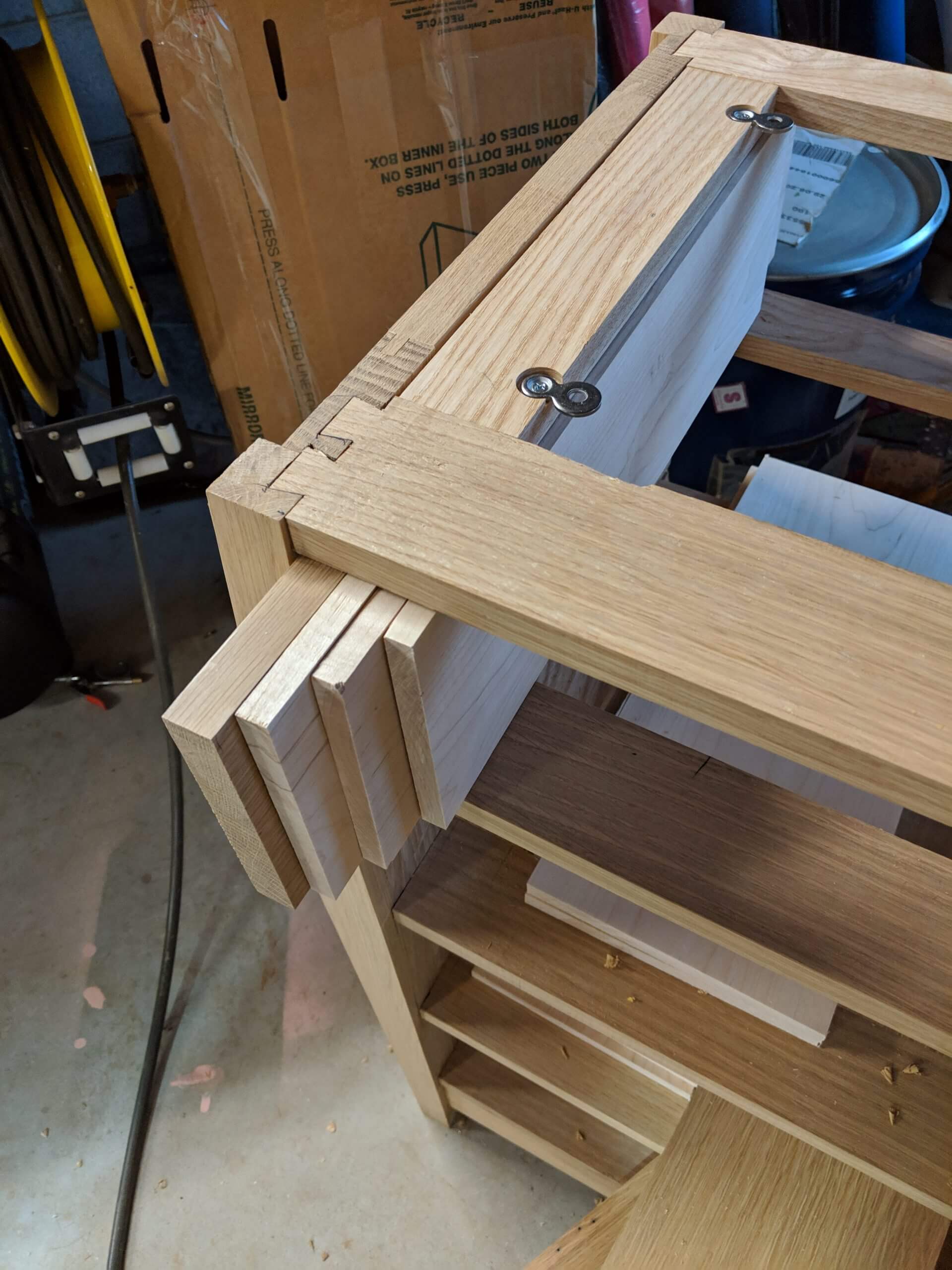
There are five Drawer Webs with the lower three being identical and the top two being similar with the exception that the topmost one will have a blind dovetail joint into the top of the stile and leg versus a sliding dovetail joint. You can see in the detail image that the only difference between the top to Drawer Webs are the layout of the dovetail. The second web from the top features a sliding dovetail and the top web features a half blind mortised into the leg/side panel.
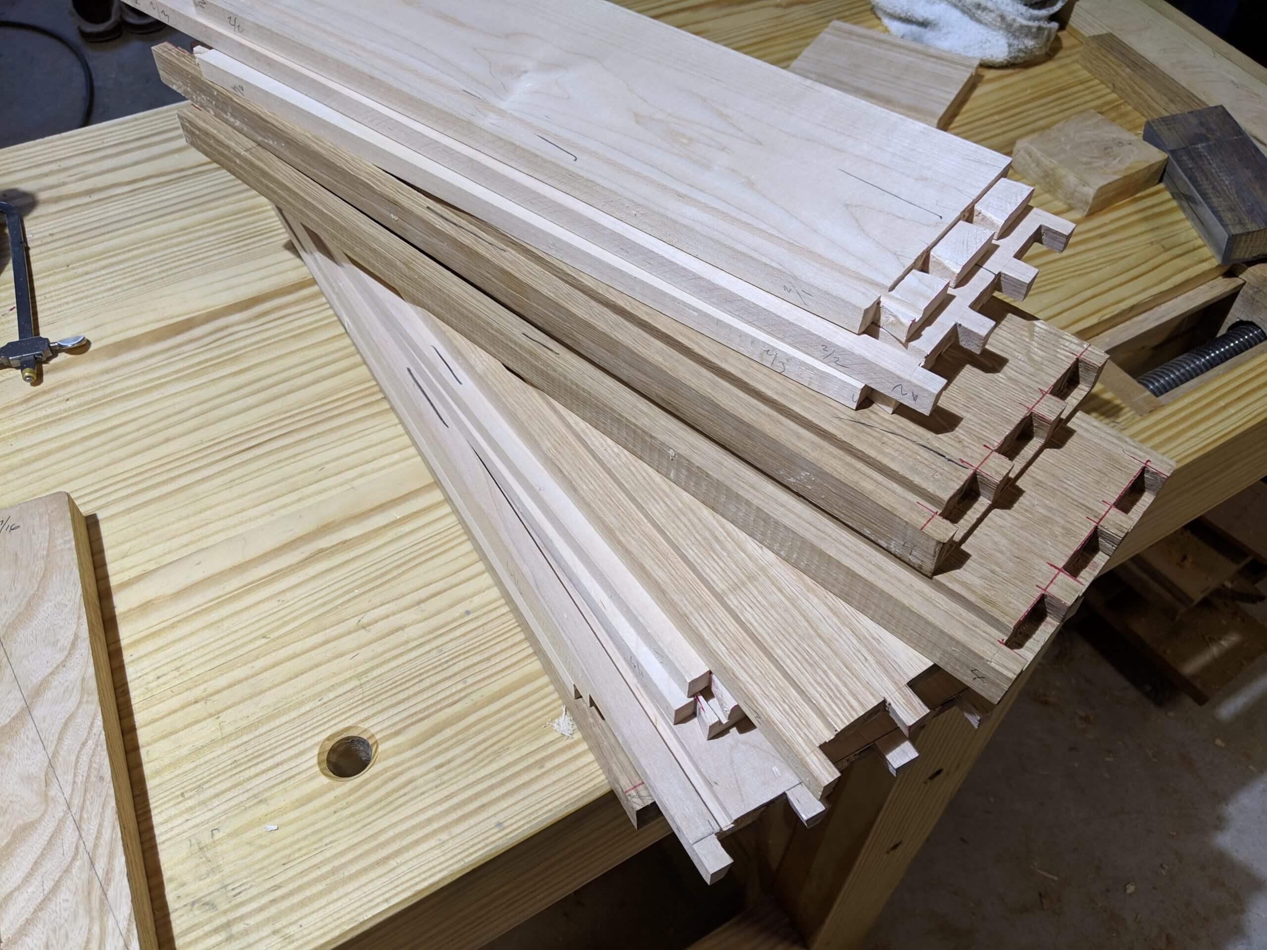
There are 90 linear feet of Drawer Webs! I made the front Drawer Dividers 3″, the back Drawer Dividers 2″, Drawer Runners 2″ and Drawer Runners in the middle of the Drawer Web 4″ to catch the edge of the drawer on each side. Vertical Drawer Dividers match the size for the front or back depending on the side they are on.
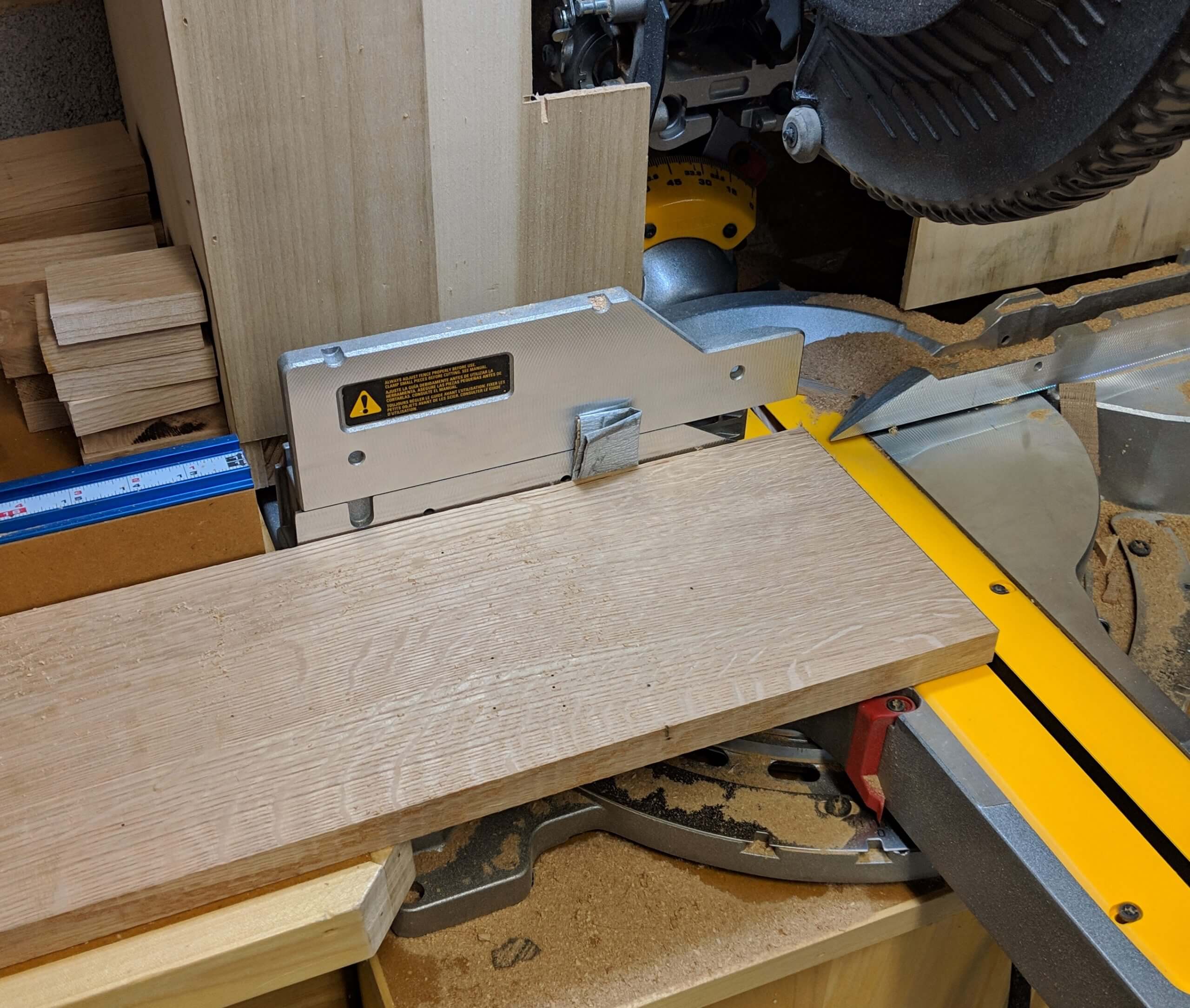
Milling the web stock will establish the width of the dresser. I cut mine to rough length at 62″ then squared one end and cut the final length to 61″. The Drawer Supports for the top web are left long as they will get a blind dovetail vertically into the top.
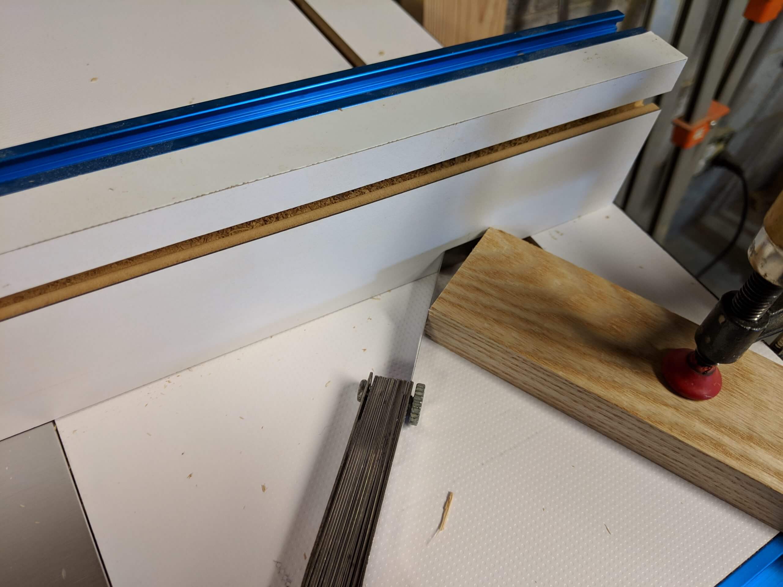
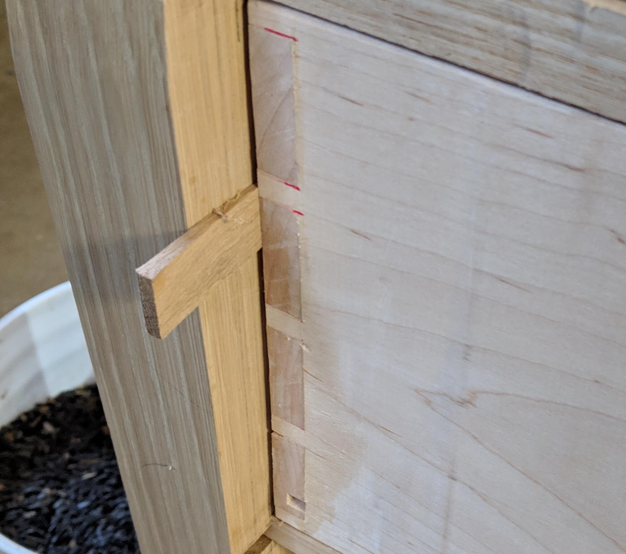
Before the ends of the Drawer supports can be cut for the dovetail, the dovetail has to be cut in the side panels. I use a 1/2″ 14 degree bit. Mark the locations on the panel will you will want your drawers. I use 7″ openings for the bottom three rows and the top row then ended up being the remainder. I marked the line on the panel for the Drawer Support location (vertical and 1/8″ in from the top and bottom of the panel) then marked the center-line for each Drawer Support and a line 1/2″ in from the front edge. The dovetail will stop at the 1/2″ point so the dovetail will not cut through the areas left for the reveal.
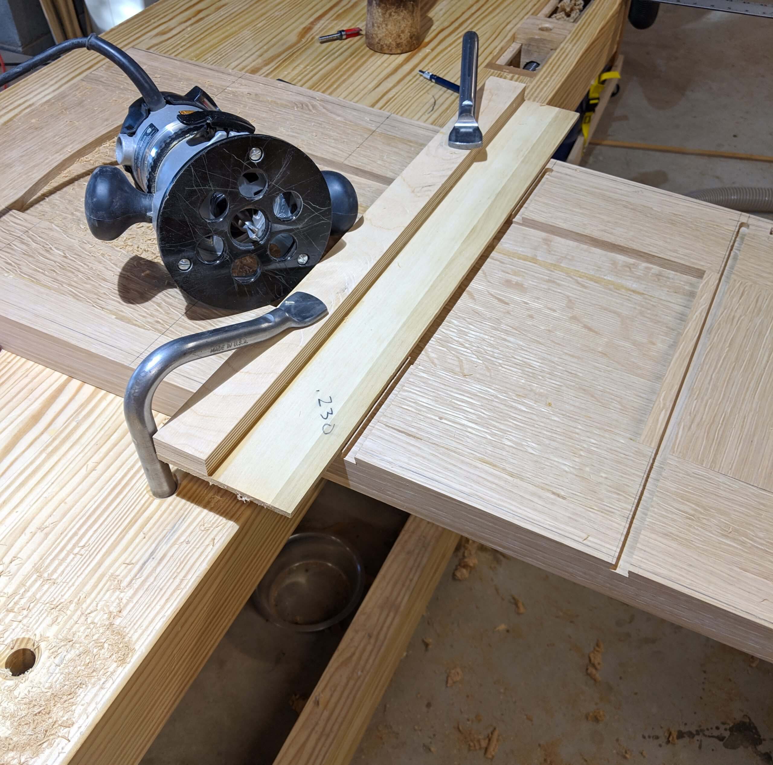
I use a zero clearance router bit template designed for a 1/2″ bit. I simply clamp this jig 1/4″ from the center-line marked on the panel and the bit is therefore centered on the line.
You have to route from the back of the panel, so orient the jig so you are not doing a climb cut, this will be on the top of the center line. Set the depth to no deeper then the depth of the center panel (my panel is set in 1/2″ from the back and I cut the dovetail 3/8″ deep). Remember when we cut the slots for the panel in the stiles and rails we move the slot as far forward as possible so the back would have the thickness needed for this dovetail.
Cut across the panel and stop when the full width of the cut hits the 1/2″ mark on the front of the side panel.
Do not route the top Drawer Support location as these will be held on by half blind dovetails that go vertically into the side panels.
Once routed, you can measure (accurately) the depth of the dovetail slot and move the bit to your router table. Raise the bit to the same height and set the fence so that the bit is 60% covered (just a starting point). On a test piece that is the same thickness as the stock you used for the Drawer Webs, cut each side and test the resulting dovetail in the slot. First check for the depth. If there is a gap at the bottom, raise the bit. If at the top, lower the bit. Cut off the first dovetail on the stock on the chop saw and make another test. Once the depth is dialed in, focus on the width. If the dovetail is too narrow, move the fence forward (covering more of the bit – leaving more wood). If it is too wide move the fence back, showing more bit.
I make fine adjustments by putting a feeler gauge between the corner of stock clamped to the surface and the fence. If I want to move the fence to the front, I put the feeler gauge in then the block, then loosen the fence and remove the feeler gauge, moving the fence to the stock. To move the fence back, tighten the stock, loosen the fence then insert the feeler gauge then snug the fence to it and tighten it.
There will be some chip-out on the bit exit, so use a backer board if the joint will be exposed.
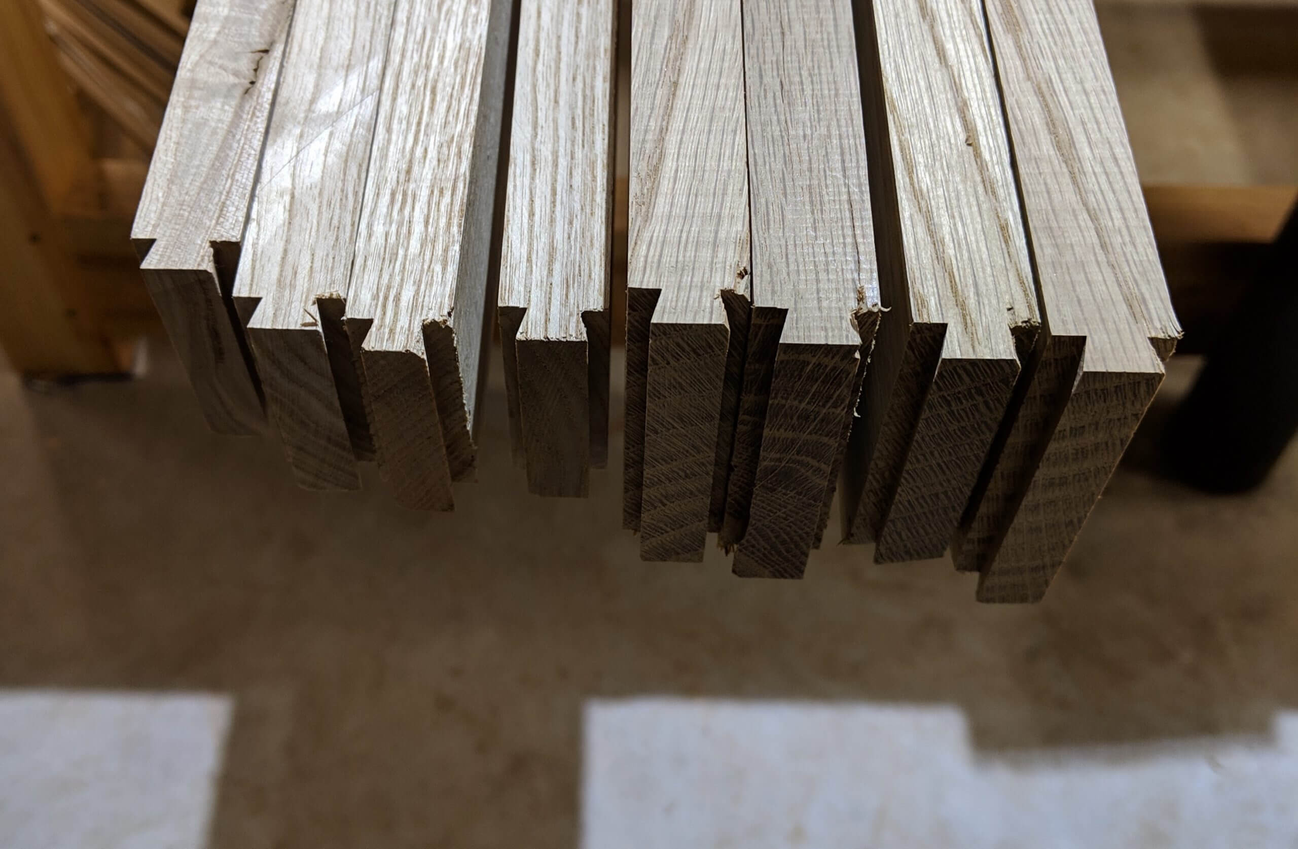
The Drawer Runners will have a 1″ long by 1/4″ thick tenon that connects to the Drawer Supports. Cut the tenons on the table saw. You could use a stub tenon for the Drawer Runners, but the edge will abut the tip of the dovetail so a shoulder on the tenon will move the mortise in and make the joint stronger.
Mark the Drawer Supports for the mortises once the tenons have been cut and you know the relief you have made on the face cuts.
There are five Drawer Webs. If you number them 1 to 5 starting at the bottom: 1 gets a dovetail grove in the top center, 2 and 3 get one on the bottom and top center, 4 gets one in the center on the bottom and one at 1/3 in from each side and 5 gets on one the bottom 1/3 in from each side. You need to stack the Drawer Webs and mark the locations for these all at once so they line up perfectly, versus measuring from an end repeatedly.
Since these are stacked on numbers 2 and 3, cut them no more than 1/4″ deep.
With the dovetail groves cut on the front and back Drawer Supports, the mortises and tenons cut and fitted, you can glue up the Drawer Webs. Check for square as you glue each. I put then on a flat assembly table so that don’t develop warps.
I trimmed 5/8″ off the front edge of the dove tail to create a blind joint for the front, remember that the dovetail slot is recessed 1/2″
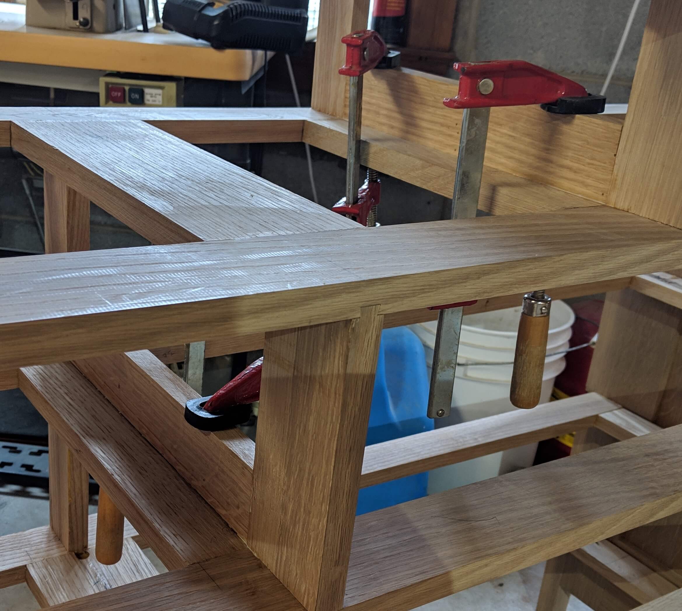
With all the webs dry, you can dry fit the carcass by inserting webs 1 through 4 from the rear. I remarked the Drawer Support reveal line on the inside of each side panel and drove the Drawer Webs home with a mallet and block until they aligned with the reveal mark.
While the sides are held in place with the dry fit, you can mark and cut the top web. Where the lower webs slide into horizontal dovetails, the top web fits into vertical ones. This is a structural joint vs a show joint and your only real objective is a tight line between the edge of the Drawer Support and the leg.
I leave the front edge of the board long by 1/32″ on each side and slope the edge slightly towards the tail so when fitted the front edge will be the part that contacts the side panel.
The last item to be made before the webs can be glued in is the front arch stretcher. This needs to be the lame length as the webs with the addition of a 1″ tenon on each end. It is easiest to simply measure Drawer Web #1 as that is the one it will butt against. When cutting the tenon, leave extra room on the top shoulder so you can slide it up and down inside the mortise. The goal is to be able to get a perfect fit between the arch and the Drawer Web. A 1/8″ allowance is fine.
After the tenons are cut, the Arch is marked with a bent strip of wood or fiberglass rod/batten, the cut on the band-saw and faired smooth.
I faired it with a hand plane, a cabinet scraper and regular scraper.
Once the arch is done you can assemble the carcass. The only item that needs a clamp is the arch piece. I assembled it by gluing in the arch, putting glue on top of the arch then fitting the top web in place without glue then putting glue into the first web slots and driving it in. Push the arch down in the mortise (that 1/8″ of play you left in the tenon) so the Drawer web clears it when driving it in. Drive it in to the point marked for the Drawer Support reveal. Once in place, the arch is clamped to the Drawer Web using the off-cut from the band-saw as a caul.
I allowed this first assembly to dry then glued in the rest of the drawer webs. When one was inserted a straight edge was used between the bottom web (already glued in) and the top web (still dry fit to keep the panels square) so that each web was driven in to a point where they all aligned.
The vertical Drawer Supports can be cut and fitted now. They should be cut to the point where they are as long as the carcass opening at the edge (don’t measure at the center as there will be some bow in the Drawer Webs) plus 2X the depth of the dovetail slot on the Drawer Support section. Cut the mating dovetail on the vertical Drawer Support and test fit them all.
When happy with the fit, remove them, plane the show face and finish sand the sides then glue them up slightly proud so you can level them with sandpaper or a plane.
Measure and cut Drawer Guides to go between the vertical Drawer Supports and simply glue them in place. The guides on the outer sides will need to be milled to the exact depth of the floating panel is inset so that the drawer has a continuous smooth surface to follow. The outer guides are simply held on with hot glue in the center as you do not want to restrict the floating panel from moving.
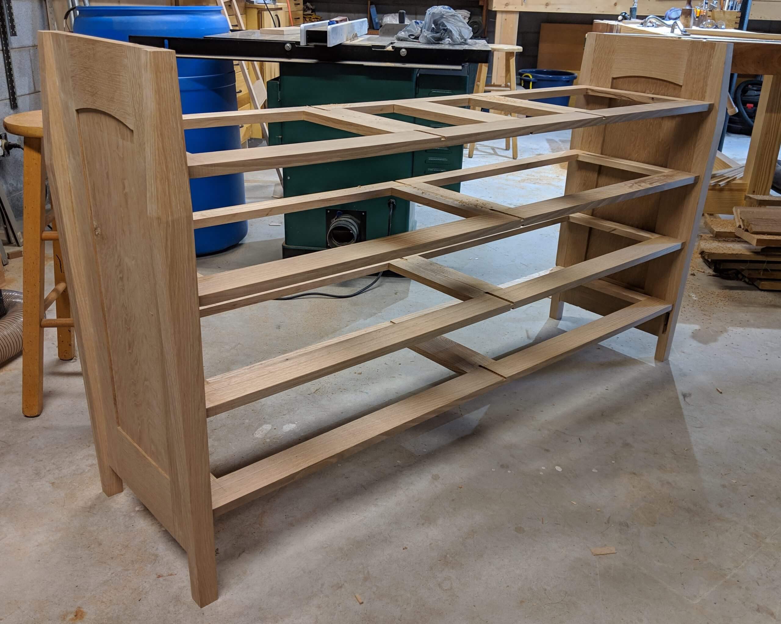
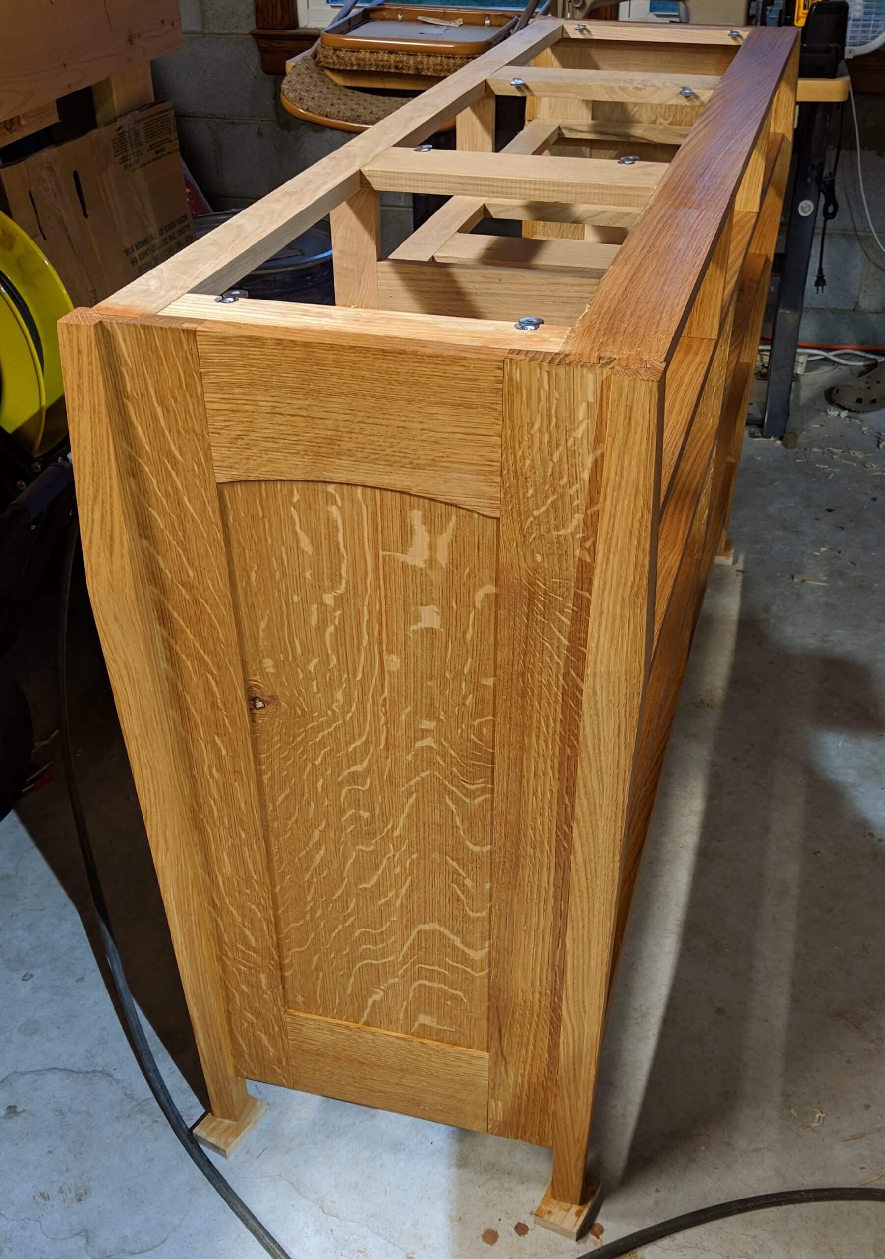
Once the Drawer Guides are installed, the carcass is done (with the exception of the back). You can finish now or wait. I recommend waiting as there will be some shop rash due to fitting of the drawers.
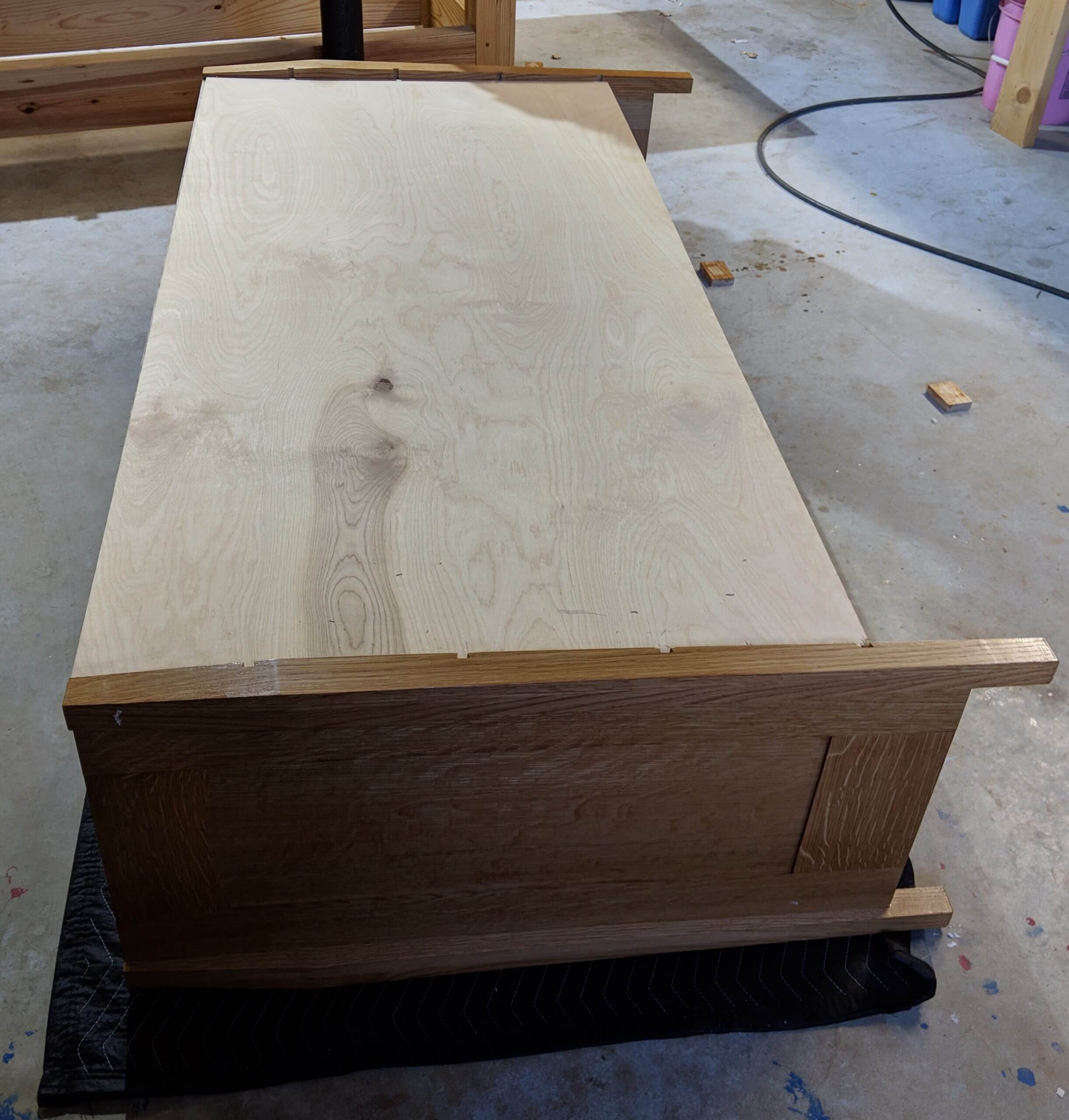
The final carcass step is to put on a back. I view this as optional, as I frequently don’t use one. For a piece this long, a back will help strengthen the piece, a a 1/4″ plywood back is glued on and held with brads while it dries. As a rule I detest metal fasteners in furniture, but in this case it is a good compromise from some elaborate clamping setup for the back.
Top
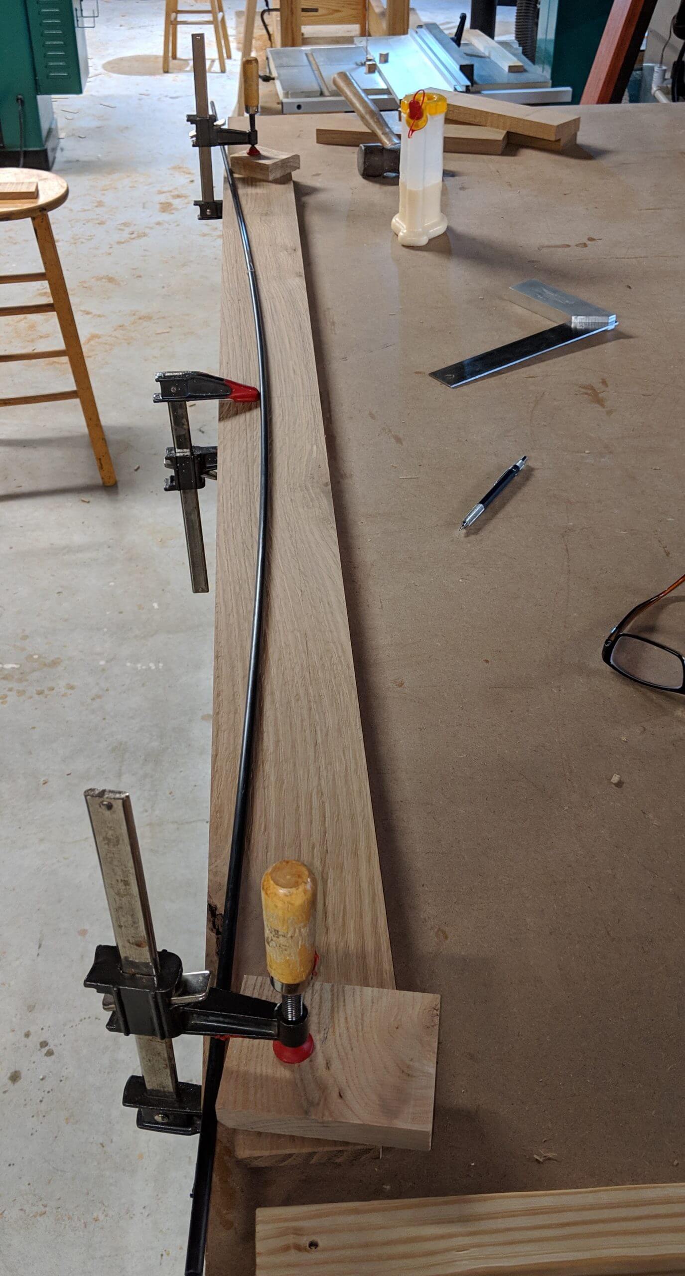
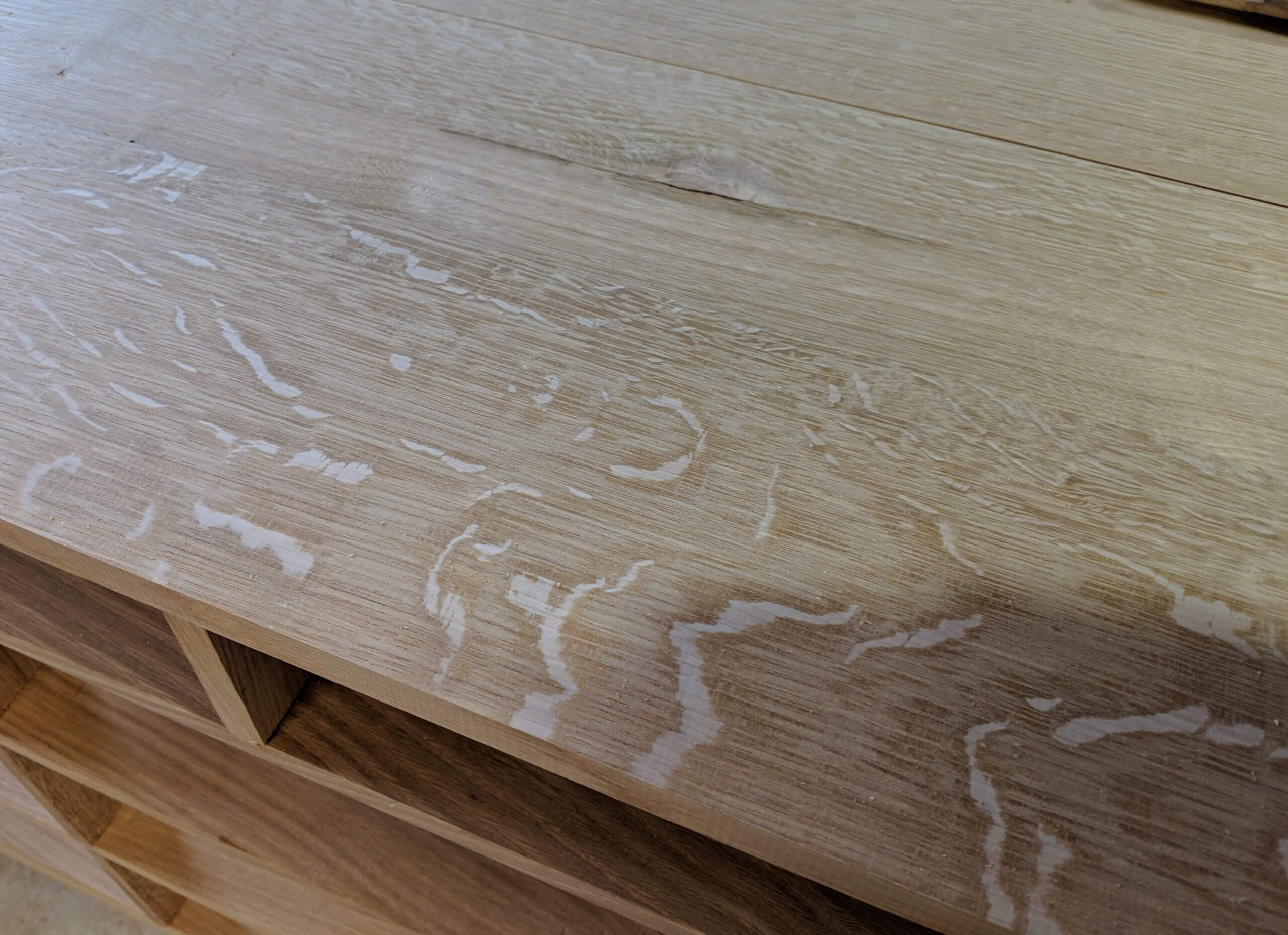
I picked out some very figured wood for the top. I rough cut it two inches longer than the width of the carcass and ripped the boards so the final top would be one inch wider than the carcass.
Given the size, I used biscuits to align the top for glue up, spacing them every ten inches.
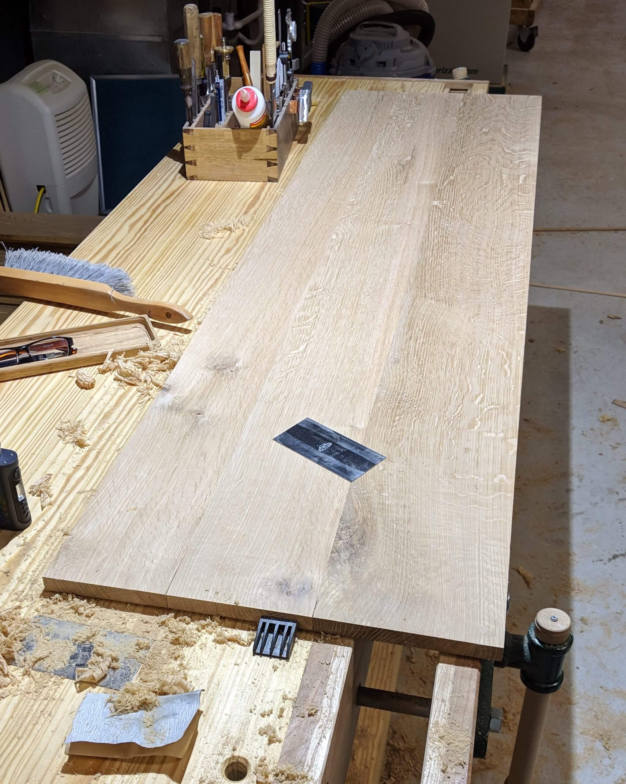
When dry you can do final surface prep to the top and start finishing each side of the top while you move on to making drawers.
I start the top finishing first as I want to apply the same finish to the underside and top and it therefore takes longer to finish then the rest of the project. Standard finish steps for me are a light sanding with 220 to expose flaws, then work the part with a scrapper or a cabinet scraper if needed, then final sand with 220 followed by stain (if used) and finish.
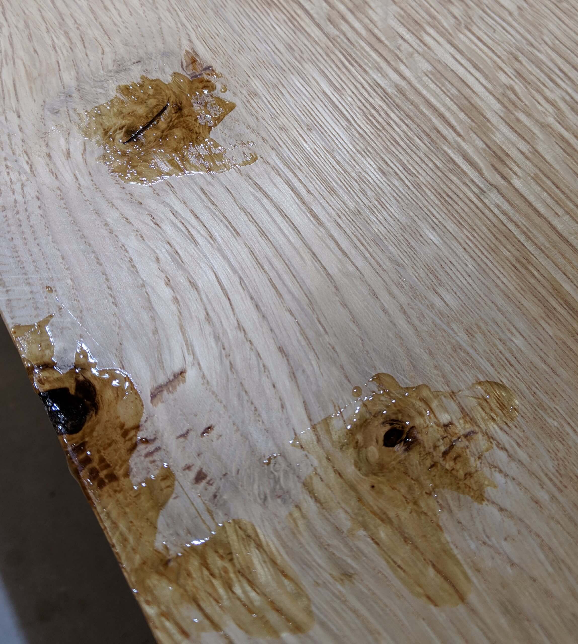
This top has a good bit of tear our due to the complex grain as well as a few knots, so after staining they were filled with epoxy.
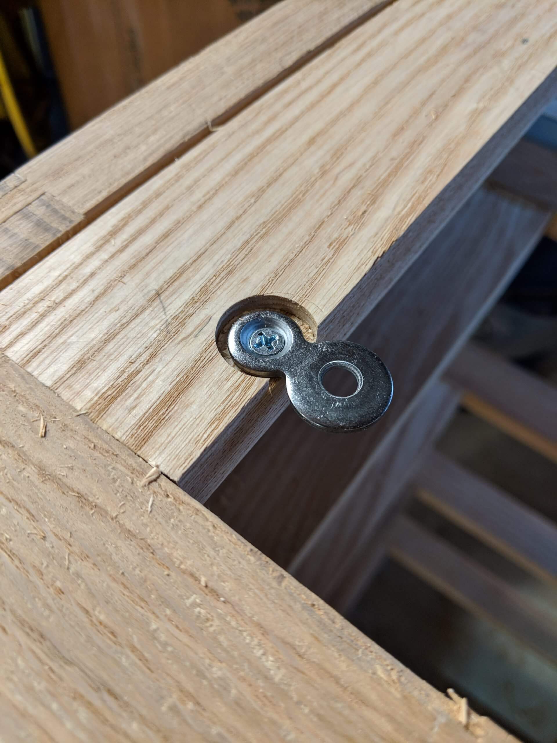
The top will be held on by figure eight washers. Drill a 1/2″ counter sink 3/16″ in from an edge then pre-drill for a screw. I used eight of them.
To aid in transport, the top is left off until the piece is in its final location. It is heavy enough as is!
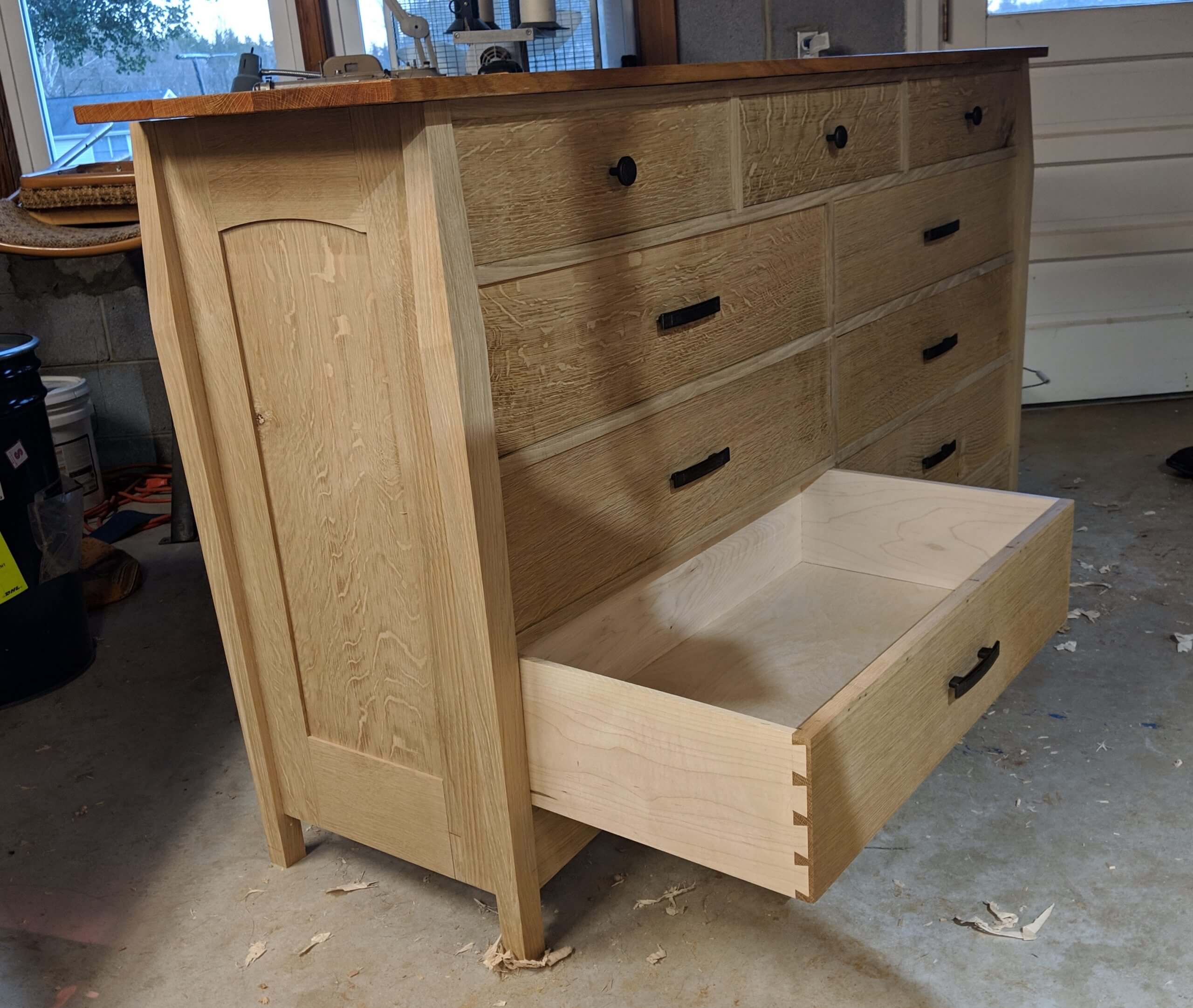
Drawers
Try as you might, the drawer openings will not be perfectly square or all the same size. Your drawer openings are intended to be square, but in reality they are more of a trapezoid of sorts but the top and bottom are likely not parallel (in an absolute sense). When I say “not square” don’t mean drastic angles, but your drawer and the opening will be off by a fraction of a degree in each direction. You want to minimize that fraction, but you non-the-less have to account for it. There are only two options then: Drawer runners with a facia front (like kitchen cabinets) or fitted drawers. For furniture I only recommend fitted drawers.
Mill your drawer face stock to the same thickness for all the drawers (it will make cutting the joints uniform and easier). I rough cut them all to at least 1″ longer in every direction. Once done, lay the faces out and arrange them for grain and color. When happy, number them and put an up arrow on the outside of each drawer part, mark a line on the bottom inside where the dado for the bottom will generally go.
Measure your drawer banks in multiple locations and determine the tallest measurement. Some of my 7″ drawers were 7 1/16″ (due to a slight bow of a Drawer web), some were 6 21/32″. Though you shoot for 7″, laying out router cut lines and positioning jigs will introduce some error. Not enough to “see” but enough that you have to take it into consideration when making mating parts. Once you have a “maximum” for a given drawer bank, rip them to that width plus 1/16 (so the blanks are all 1/16 taller than your widest measurement). Once ripped, use the miter saw to square the edge that will be against the panel side (you can pick either side for the top center drawer). I start with the panel side as it is the “most square” of the joints.
Offer the drawer face to the opening it is intended for and note how much each end extends too high. Ideally the overage is the same, but it usually varies. Plane the top (or bottom at this point as you are doing full passes) until the height of the face is reduced enough for one corner to slip into the opening. Press the bottom firmly to the drawer web. Look at the top face and see where the fit falls off (middle, just after the corner that fits etc) and look at the bottom face to see if it is in contact all the way across. Typically the bottom of the drawer face and the drawer web are straight and you can confine your tuning to the top. I note where the top is falling out of fit and then from from that point to the tall corner with a plane – then retest. Continue this until each end fits with resistance.
Once the drawer face has been fitted for height, you can fit it for width. It is still about an 1″ too long at this point. Press the face into the opening using the side that you cut square. Note how the fit is. You will typically have 1/2 to 1 degree of slop for a perfect fit. Note where it hits and where the gap is and plan off the portion that is making contact until the entire side is making contact. Just as with the height, plane and test, plan and test. With a friction fit on the top and bottom, you want to slide the face up against the panel edge and have no gap.
Once the outer edge has been fitted, you can fit the inner edge. I insert the face into the fitted edge by 1/4″ (no too much as you don’t want the face held at an extreme angle) and hold it firmly against the vertical drawer support then reach around and mark the face running a pencil against the vertical drawer support.
This too will not be a square cut. It will be close but will likely be off a degree. To make the cut, I position the drawer face on the miter saw and use a small ship to move the face in and out of the fence until the line aligns with the path of the blade. You do not want to cut to the line. Leave 1/32″ or so so you can manually fit the part.
Take the fresh cut face to the carcass and test it in the opening. It will not fit, but you can note the overlap and then hand plane it until it fits. Just as with the height, full passes until one corner fits in, then work the other corner.
You are shooting for a friction fit on four sides.
Once fitted, they will be the reference point for milling the rest of the drawer parts. You can rip your sides to the height of each side of the face and make your back a duplicate of the face.
For the backs and sides I started with 5/4 maple. I wanted ash to go with the rest of the secondary wood in the project, but the lumber yard was out of stock in widths over 7″. I re-sawed the maple down 5/8″ then surfaced them to 1/2″ thick. Each side was ripped to match the height of the drawer face at that side and the back was cut to be identical to the face. Each part was then test fit and adjusted with a plane to achieve a friction free fit.
I used through dovetails in the back and half blind in the front. Rather than include those steps here, I have a separate write up that covers it (with images from this project and another). You can find it here.
After the dovetails are cut, I cut a dado for the drawer bottom. I do this with two passes on the table saw with the blade raised to 1/4″. The outermost pass starts at the base of the tail, so it it hidden in the final drawer. Dry fit your drawers and cut bottoms out of 1/4″ plywood that are the dimensions of your drawers plus 7/16″ in each direction (you have 1/2″ clearance total in the dados).
I used a trick to fit them a bit easier that I will share. The issue is if you have a half a degree of out of square in the carcass, and make a perfectly square drawer, you have a bit more hand work to fit it (or if you think your drawer is perfectly square and it is off a small amount). To accelerate this process, I assembled the drawer and dry fit it, fitting the bottom at the same time. I test the dry fit drawer to the opening and plane it to a good fit. When it will fit, then I remove one side at a time and glue it up and while the glue is wet, put it in the carcass slot so it can adopt any minor skew that the carcass has. To align the reveal in the front, I made a collection of small wedges that would move the back of the drawer in small amounts to make minor adjustments to the reveal. Drawers glued up this way needed considerably less hand work for a clean fit.
When the drawers are glued up, they will be generally the size of the opening but will likely be too tight. They will also have alignment issues as the footprint of the opening, though designed square, may be off a half of a degree here and there and a perfect fitting drawer may have an uneven reveal, even using the wet slotting method above.
You fix this by inserting the drawer, then noting where it binds, then adjusting the sides top and bottom as needed with a block plane. When the drawer will insert fully, you can adjust the angle of the reveal to that it is parallel to the carcass face. You adjust the angle by removing wood with a plane from the back corner in order to rotate the drawer into square with the face. Removing wood from the left back will open up the gape in the right front. You will have to make small adjustments. It is an iterative process of testing, adjusting and repeating.
Some tips to help: Push the drawer in till it binds. move the front up and down and left to right. Is there movement? If so the bind is at the back. If not look at the part of the drawer entering the opening. A lack of minute up and down movement indicates the sides are bound on the top and/or bottom. A lack of minute left and right movement indicates the sides are bound on the flat face. You can typically look at the fit between the drawer and the opening and spot the bind. If the front moves a bit in each direction, but when you grasp the back it is firm, the bind is in the back. Find the spot, adjust it and repeat. typically you get further each test until it slides in. Binds that are had to spot, but need to be addressed are the rear against the drawer support and the sides agains transition in the carcass (where one part of a drawer web meets another and there is a slight lip that you missed when sanding).
A slight chamfer on the back on all four edges help with the fitting.
Prior to finishing, I mount the hardware with a simple jig to align the holes. I make a jig based on the hole spacing of the hardware and the depth needed to reach the center of the drawer face. I cut a notch out of the jig so I can see the center point marked on the drawer face.
Finishing
Hardware is installed then removed so that the drawers can be finished. I install it now to avoid additional shop rash caused by working the drawers after finishing.
The hardware is the larger Arts and Crafts drawer pull from Hickory Hardware and the small knob in the same series.
The drawers are finish sanded to 220 grit then the inside and outside are given a coat of shellac.
The carcass is gone over one more time with a card scraper and 220 grit and the bottoms of the feet are chamfered. When you are satisfied that all the rough spots and shop rash have been addressed you can stain or go directly to finish. When staining, I wipe stain onto the oak and not the drawer sides, though it is not critical (I use a folded corner of a rag).
I used one coat of Minwax Pecan Stain then four coats of Osmo Hard Wax Oil.
Finally, the sides and bottoms of the drawers as well as all drawer contact surfaces in the carcass get a thick coating of paste wax to help with sliding.
The back is put on last and is simply 1/4″ plywood. You can use 1/2″. I glued it to the Drawer Webs to help form a beam like structure.
Errors/Changes
So what went wrong? Well:
- I put one panel stile on the router wrong side down and had to splice in a small piece
- One of the female cuts for a sliding dovetail in the top Drawer Web was in the wrong place (I have no idea how I did that) and I had to fill it and manually fit the divider.
- Drawer 2 (center top row) had a mis-aligned drawer box, likely due to the above referenced error and I had to plane off a good 1/8″ to get it square, as such I had to glue in a wedge in the back to help it align right.
- While installing the Drawer Webs, the bottom one was very tight and took a great deal of pounding one side, so much so that it broke the glue joint on the bottom rail of the side panel. I caught it in time to re-glue it and clamp it up.
- Two drawers were so dead on in fit that they were tight after finishing and I had to use a plane. Once the piece stabilizes after the summer I will re-fit all of them and touch up any finish issues.
I don’t think I would change the design any after building it. It is functional, fits the style points of the Arts and Crafts movement and shows well next to pieces from the period. The wood is locally harvested and has some knots. I used them. Drawer 3 has one, Drawer 9 has two, the Bottom Arch has two and there are a few in the top. Up close the grain around them is interesting and I like the look of the wood.
Build time was three months, generally working one weekend day a week and some time in the evenings.
Watched one of your YouTube videos and ended up here. Fantastic work all the way around!
Thanks man. I did not do a video of the dresser. It remains one of my signature items. I still love it.